14.2 Accuracy of Vibration Measurements
A basic measurement system consists of a transducer with a conditioner (which senses the signal, and converts to a measurable quantity like voltage or charge with some amplification), an analog-to-digital converter, and a processing and display unit as shown in Figure 14.8. We shall focus our attention in the error involved in transforming the analog signal to the digital signal.
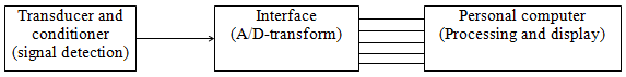
Figure 14.8 A basic measurement system
The vibration signal from the vibrating structure is detected and converted into a measurable physical quantity by transducers. In a rotating machine, rotor displacements in two orthogonal directions and a rotating speed are detected as voltage variations. The output signal x(t) from the transducer is an analog signal that is continuous with time (it is similar to a theoretical function that is defined for all possible values of its variables) as shown in Figure 14.9(a). However, the signal is discretised when it is acquired by computer through an A/D interface as shown in Figure 14.9(b), where the solid line represents the actual signal and circles represent the digitized signal data at grid nodes. It can be seen that depending upon the resolution of the instrument the accuracy of the acquired data will depend, finer the grid more the accuracy and vice a versa, since the digitized data will be aquired only at the grid points. A digital signal is discretised in both time and magnitude. This digital signal is a series of discrete data {xn} obtained by measuring (called sampling) an analog signal instantly at every time interval Δt and is given as xn = x(nΔt), where n is an integer. This interval Δt is called a sampling interval, which is generally constant. Discretization in magnitude is called quantization, and the magnitude is represented by binary numbers (unit: bit. A bit (short for binary digit) is the smallest unit of data in a computer. A bit has a single binary value, either 0 or 1. Although computers usually provide instructions that can test and manipulate bits, they generally are designed to store data and execute instructions in bit multiples called bytes. In most computer systems, there are eight bits in a byte). Binary describes a numbering scheme in which there are only two possible values for each digit: 0 and 1. In binary numbers the digits' weight increases by powers of 2, rather than by powers of 10 as in the more familiar decimal numbers. In a digital numeral, the digit furthest to the right is the "ones" digit; the next digit to the left is the "twos" digit; next comes the "fours" digit, then the "eights" digit, then the "16s" digit, then the "32s" digit, and so on. The decimal equivalent of a binary number can be found by summing all the digits. For example, the binary 10101 is equivalent to the decimal 1 + 0 + 4 + 0 +16 = 21.
|
|
(a) Analog signal |
(b) Digitised signal |
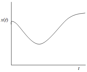
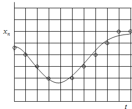
Figure 14.9 The analog and digital signals
Now we shall highlight some other errors which may be involved in measuring the vibration signal. When an analog signal x(t) is changed into a sequence of digital data {xn} (n = 0, 1, 2, …, N) a virtual (or imaginary) wave is obtained if a fast signal is sampled slowly. For example, when a signal illustrated by the full line is sampled as shown in Figure 14.10(a) with black dots, a virtual signal wave as shown in Fig. 14.10(b) appears, although it is not contained in the original signal.
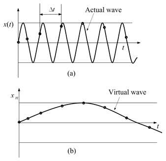
Figure 14.10 Aliasing effect on a fast signal while slow sampling
(a) 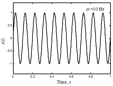
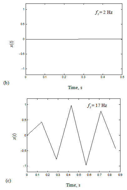
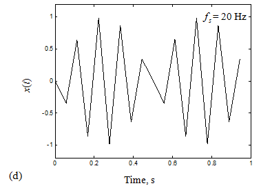
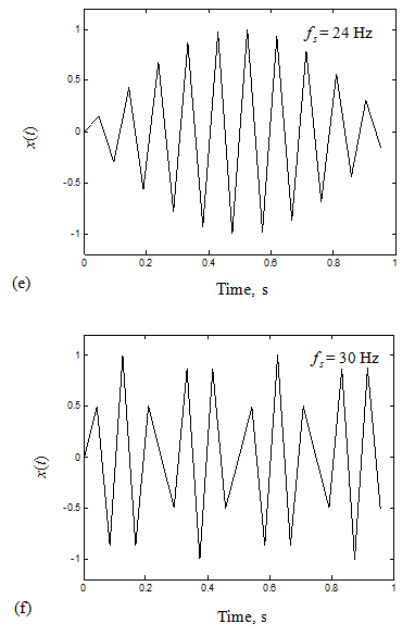
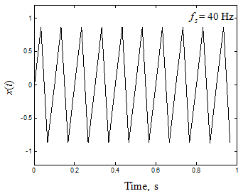
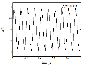
Figure 14.11 Illustration of aliasing effect and sampling frequency in a sinusoidal signal