Event driven simulation for the circuit (of Figure 7) for input pattern I1=1, I2=1 and fault s-a-1 in OG2 is shown in Table 4. It may be noted that the fault s-a-1 in OG2 is detected by input pattern I1=1, I2=1 at output O1; in case of fault O1=1, were as in case of normal circuit O1=0. Also, all four steps of the event driven simulation are required to detect the fault. So, detecting s-a faults using event driven fault simulation may not always save computation time, as in the worst case all the steps may be needed.
Table 4. Event driven simulation for circuit of Figure 7 for input pattern I1=1, I2=1 and s-a-1fault in OG2
| Time |
|
Activity List |
| t=0 |
|
|
| t=1 |
I2(G1)=0,I2(G2)=0 |
|
| t=2 |
OG1=0 ,O2=0 ,OG2=1 |
|
| t=3 |
O1=1 |
|
Event driven simulation for the circuit (of Figure 7) for input pattern I1=1, I2=1 and fault s-a-0 in I2(G1) is shown in Table 5. Like s-a-0 fault in I2, s-a-0 fault in I2(G1) is detected by I1=1, I2=1 at O2 and the fault simulator requires up to t=2 steps.
Table 5. Event driven simulation for circuit of Figure 7 for input pattern I1=1, I2=1 and fault s-a-0 fault in I2(G1)
| Time |
|
Activity List |
| t=0 |
|
|
| t=1 |
I2(G1)=0,I2(G2)=0 |
|
| t=2 |
OG1=0 ,O2=0 ,OG2=1 |
|
| t=3 |
Not Required as O2=0 in faulty situation while O2=1 in normal condition |
|
Serial fault simulation is simple, however as discussed earlier, for n faults the computing time is O(  ). With fault-dropping, this time can be significantly lower, especially if many faults are detected (and dropped) by random patterns used earlier. >> we will see advanced algorithms to reduce the complexity of fault simulation, mainly using two points
- Determine in one simulation, more than one fault if they can be detected by a given random pattern
- Use information generated during simulation of one random pattern for the >> set of patterns.
Before we go for the advanced algorithms, a small question remains. When we are talking of event driven simulation, there is no question for nets being stuck at 0 or 1. So how can we use standard event driven simulator to simulate circuits having stuck at faults. Let us look at Table 3, t=1. We may note that I2(G1)=0, I2(G2)=0, because of the s-a-0 fault in I2; under normal condition I2(G1)=1, I2(G2)=1. It is very obvious to find how the values are obtained in faulty case. However, we need to see how we can use event driven simulator to simulate circuits with stuck at faults. It is to be noted that we cannot modify the simulator algorithm to handle faults; instead we will modify the circuit. Modifying the circuit for simulating stuck at faults is extremely simple. If a net I say, has a s-a-0 fault, we insert a 2-input AND gate with one input of the gate fixed to 0 and the other input of the gate is driven by I. The gate(s) previously driven by I is now driven by output of the AND gate added. Similarly, for s-a-1 fault a 2-input OR gate with one input of the gate fixed to 1 is added.
Figure 8 illustrates insertion of the stuck at faults in the circuit shown in Figure 7. s-a-0 fault at I2 is inserted as follows. A 2-input AND gate with one input connected to 0 and the other to I2 is added. Now the newly added AND gate drives G1, which was earlier driven by I2.
Similarly, a 2-input OR gate with one input connected to 1 and the other to OG2, inserts s-a-1 fault at OG2. Now the newly added OR gate drives G3, which was earlier driven by OG2.
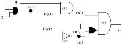
Figure 8. Insertion of faults in the circuit of Figure 7 for fault simulation in event driven simulator
To summarize, with simple modifications of the circuit, an event driven simulator can determine the output of a circuit with s-a-0 and s-a-1 faults. Henceforth, in our lectures we will not modify the circuits by inserting gates for fault simulation of stuck at faults; we will only mark the faults (as before by circles) and assume that the circuit is modified appropriately.