1.Introduction
In the last lecture we learnt how to determine a minimal set of faults for stuck-at fault model in a circuit. Following that a test pattern is to be generated for each fault which can determine the presence/absence of the fault under question. The procedure to generate a test pattern for a given a fault is called Test Pattern Generation (TPG). Generally TPG procedure is fully automated and called Automatic TPG (ATPG). Let us revisit one circuit discussed in last lecture and briefly note the steps involved in generating a test pattern for a fault. Consider the circuit in Figure 1 and s-a-1 fault at the output of gate G1. Three steps are involved to generate a test pattern
- Fault Sensitization: As the output net of G1 is stuck-at-1, we need to drive it to 0 to verify the presence/absence of the fault. So output of G1 is marked 0.
- Fault Propagation: Affect of the fault is to be propagated to a primary output (Output of G6, in this example). In this case, the propagation path is ``output of G1 to output of G6”. For enabling this fault to propagate by this path, other inputs to G6 (from gate G2, G3, G4 and G5) are to be made 1. Affect of fault at the primary output is “1 if fault is present and 0 if fault is not present”.
- Justification: Determination of values at primary inputs so that Fault sensitization and Fault propagation are successful. To sensitize fault (0 at output of G1), I1=0 and I2 through I5 are 1. To make outputs of gates G2, G3, G4 and G5 1, primary inputs I6 through I25 are made 1.
So test pattern is I1=0 and I2 through I25 are 1. It may be noted that there are 2 5 -1 choices to sensitize fault (apply 0 at output of G1); all input combinations of G1 except I1=1, I2=1, I3=1, I4=1 and I5=1. However, to propagate the fault there is only one pattern (primary inputs I6 through I25 are made 1). TPG procedure would generate any one of the patterns given in Table 1
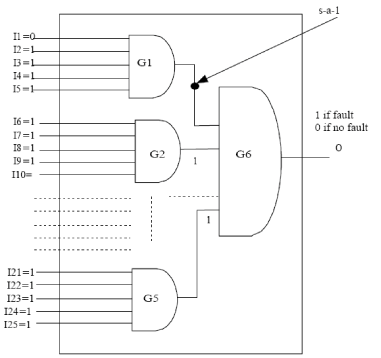
Figure 1. s-a-1 fault in net OG1 with input test pattern
Table 1. Test patterns for the s-a-1 fault in the circuit of Figure 1
| Test Pattern No. |
Test Pattern I1 I2 I3 I4 I5 I6……………………..................I25 |
Output | |
| 1 |
|
1 if fault 0 if no Fault |
|
| 2 |
|
1 if fault 0 if no Fault |
|
| ..................... |
|
.................... | |
| 225 | 1 1 1 1 0 11111111111111111111 | 1 if fault 0 if no Fault |