Compiled Code Simulation
As the name suggests, Compiled Code method of simulation involves describing the circuit in a language that can be compiled and executed on a computer. The circuit description can be in a Hardware Description Language such as VHDL or Verilog [4] or simply described in C. Inputs, outputs and intermediary nets are treated as variables in the code which can be Boolean, integer, etc. Gates such as AND, OR, etc., are directly converted into program statements (using bit wise operator). For every input pattern, the code is repeatedly executed. Figure 3(A) shows a simple digital circuit and the corresponding C code required for its simulation is given in Figure 3(B). It may be noted that all 4 inputs, two intermediary nets (OG1 and OG2) and Output are represented as integer variables. All the gates are converted into single statements using bit wise operators.
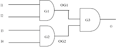
Figure 3(A). A Digital Circuit
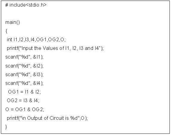
Figure 3(B). C code for the circuit of Figure 3(A) required for compiled code simulation
Compiled code simulation is one of the simplest techniques of all circuit simulators. However, for every change in input the complete code is executed. Generally, in digital circuits, only 1-10% of signals are found to change at any time. For example, let us consider the circuit given in Figure 3(A) where input I1 changes from 1 to 0; this is illustrated in Figure 4. We can easily see that change in input modifies only 3 out of 8 lines. On the other hand a compiled code version would require reevaluation of all the 8 variables. >> we will discuss event-driven simulators which may not require evaluating all gates on changing of an input.
Figure 4. Changes in signal values in a circuit for change in input