3.1 Serial Fault Simulation
This is the simplest fault simulation algorithm. The circuit is first simulated (using event driven simulator) without any fault for a random pattern and primary output values are saved in a file. >>, faults are introduced one by one in the circuit and are simulated for the same input pattern. This is done by modifying the circuit description for a target fault and then using event driven simulator. As the simulation proceeds, the output values (at different primary outputs) of the faulty circuit are dynamically compared with the saved true responses. The simulation of a faulty circuit halts when output value at any primary output differs for the corresponding normal circuit response. All faults detected are dropped and the procedure repeats for a new random pattern. This procedure is illustrated in Figure 7. The circuit has two inputs and two primary outputs. For the random input pattern I1=1, I2=1 the output is O1=0, O2=1 under normal condition. Now let us consider a s-a-0 fault in I2. Event driven simulation (with scheduled events and activity list) for the circuit for input pattern I1=1, I2=1 and s-a-0 fault at I2 is shown in Table 3. It may be noted that that event driven simulation for this circuit requires 4 steps (t=0 to t=3). However, at step t=2, we may note that value of O2 is determined as 0, but under normal condition of the circuit O2 is 1. So, the s-a-0 fault in I2 can be detected by input pattern I1=1, I2=1 when O2 is 0. In other words, for input pattern I1=1, I2=1 the s-a-0 fault in I2 is manifested in primary output O2. As the fault is manifested in at least one primary output line, we need not evaluate other outputs (for that input pattern and the fault). In this example, for s-a-0 fault at I2 (after t=3 step of simulation), input pattern I1=1, I2=1 gives O1=0, O2=0; so fault can be detected ONLY at O2. However, we need not do this computation----“if only one primary output line differs for an input pattern under normal and fault condition that input pattern can test the fault”.
So, s-a-0 fault at I2 is dropped (i.e., determined to be tested by pattern I1=1, I2=1) after t=2 steps of the event driven simulation of the faulty circuit. To summarize, detection of stuck at faults in a circuit using event driven fault simulation may save computation time, as for many cases all the steps need not be carried out.
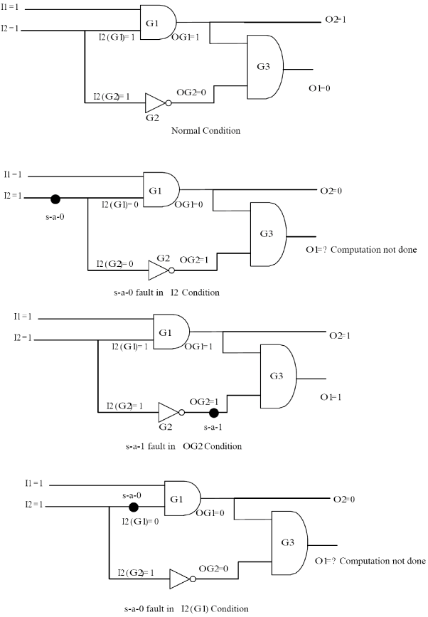
Figure 7. Illustration serial fault simulation
Table 3. Event driven simulation for circuit of Figure 7 for input pattern I1=1, I2=1 and s-a-0 fault in I2
| Time |
|
Activity List | |||
| t=0 |
|
|
|||
| t=1 | I2(G1)=0,I2(G2)=0 |
|
|||
| t=2 | OG1=0 ,O2=0 ,OG2=1 |
|
|||
| t=3 | Not Required as O2=0 in faulty situation while O2=1 in normal condition |
Now we discuss the cases for the other faults shown in Figure 7.