Answer .
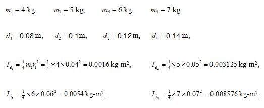
Example 8.7 Find transverse natural frequencies and mode shapes of the rotor system shown in Figure 8.32. B1 and B2 are bearings, which provide simply supported end condition and D1 , D2 , D3 and D4 are rigid discs. The shaft is made of the steel with the Young's modulus E = 2.1 (10)11 N/m2 and uniform diameter d = 20 mm. Various shaft lengths are as follows: B1D1 = 150 mm, D1D2 = 50 mm, D2D3 = 50 mm, D3D4 = 50 mm and D4B2 = 150 mm. The mass of discs are: m1 = 4 kg, m2 = 5 kg, m3 = 6 kg and m4 = 7 kg. Consider the shaft as mass-less. Consider discs as thin and take diameter of discs as d1 = 8 cm, d2 = 10 cm, d3 = 12 cm, and d4 = 14 cm, however, neglect the gyroscopic effects.
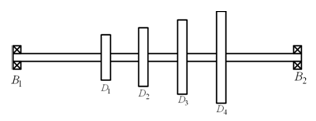
Figure 8.32 A multi-disc rotor system
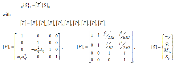
Solution : The discs have the following data
The shaft has EI = 1649.34 N-m2 and following dimensions according to station numbers
![]()
Now the overall transformation of the state vector can be written as
 |
(a)
(b)
(c) |
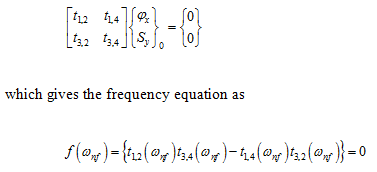
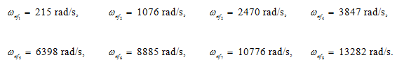
From Table 8.3, we have the eigen value probelm for the simply supported boundary conditions, as
On solving the roots of above function by the root searching method, it gives the following natural frequencies
From Table 8.3, the eigen vector can be obtain from the following equation
 |
(f) |
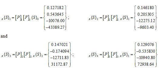
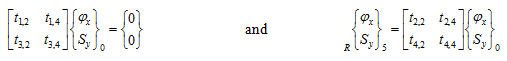
For example for a particular natural frequency from equation (d) and (f), we have
 |
(g) |
Now on choosing fx = 1 as reference value, from equations (g) and noting the boundary condition, we get the state vector at 0th and 5th station as
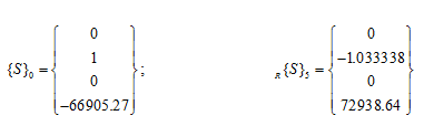
At other stations also the state vectors can be obtained as