Now for the unbalance response from equations (a), (e), (g) and (f); we have
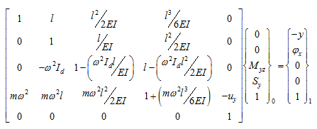 |
(j) |
The first two rows and the last three rows will give
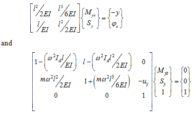 |
(k)
(l) |
The form of equations (k) and (l) is similar to that given in Table 8.4. Equation (k) can be written as
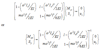 |
(m)
(n) |
Equation (n) can be used to get the bending moment and the shear force due to unbalance force. Hence, on substituting equation (n) into equation (k), we get
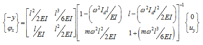 |
(o) |
Equation (o) can be solved for a particular spin speed to get the unbalance response (y and fx ). Then in the similar way the spin speed can be varied to get the variation of the unbalance response with the spin speed. A plot of the y and fx with respect to the spin speed of the rotor is given in Figures 8.24(a and b). The resonant condition can be seen as large amplitudes of vibration and it indicate critical speeds. A similar plot can be obtained from equation (n) for Myz and Sy are shown in Figs. 8.24(c and d). It can be observed from all four plots that critical speeds are same as natural frequencies obtained by free vibration analysis (ωnf1 = 195.4 rad/s and ωnf2= 3046.2 rad/s). In the plots of the shear force and the bending moment at support, anti-resonances can be seen in between the two critical speeds. This indicates that two modes of vibrations have cancelling effects on the shear force and the bending moment. The frequency at which the anti-resonance occurs for the shear force is not same as that of the bending moment. It indicates that it is not a system characteristics and its location may change for different unbalance force, however, critical speed have fixed frequencies since it is system characteristics.
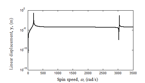
Figure 8.24(a) Variation of the unbalance translational response with the spin speed
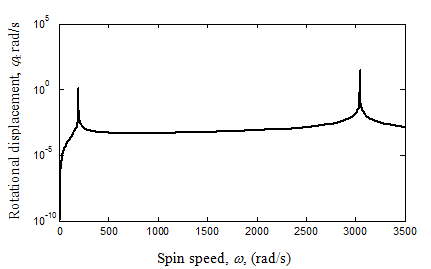
Figure 8.24(b) Variation of the unbalance rotational response with the spin speed