The following boundary conditions are applied for the present case (Figure 8.25)
(e) |
On application of boundary conditions in equation (c), the following set of equations is obtained
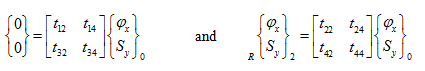 |
(f) |
From the first set of equations (e), the frequency equation takes the following form
(g) |
On substituting equation (e) into equation (g), we get
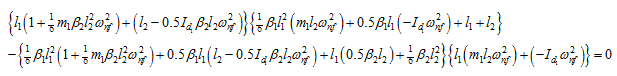
which simplifies to
(h) |
After substituting numerical values in equation (h), we get natural frequencies of the rotor system as
![]()
The relative translational and rotational displacements, and the bearing and shaft reaction forces:
(i) For ωnf1 = 29.45 rad/sec: Let us assume φz0 = 1 rad, from equation (f), we have
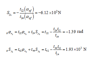
Now state vectors at stations 0 and 2 are completely known. Hence, state vectors at the left and right of station 1 can be obtained as
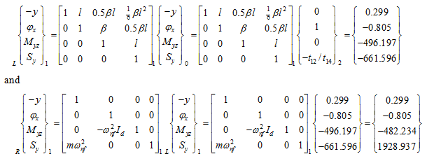
It should be noted that for relative amplitudes of displacements, reaction forces and moments have no quantitative significance. In fact, estimation of unbalance responses would give exact value of loads at various stations of the shaft.
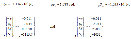
(ii) For ωn2 = 289.23 rad/sec: Let us again assume φz0 = 1 rad. For this case also, on same lines as for the previous case, we get following results
Example 8.6 Find transverse natural frequencies and mode shapes of a two-disc rotor system shown in Figure 8.26. B is a fixed end, and D1 and D2 are rigid discs. The mass of discs are: m1 = 5 kg and m2 = 2 kg, and the diametral mass moment of inertia are: Id1 = 0.03 kg-m2 and Id2 = 0.01 kg-m2 . The shaft is made of the steel with the modulus of elasticity E = 2.1 (10)11 N/m2 , and of the uniform diameter d = 10 mm. Shaft lengths are: BD1 = 50 mm, and D1D2 = 75 mm. Consider the shaft as mass-less.
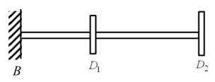
Figure 8.26 An overhung two rotor system
Solution : Figure 8.27 shows station numbers with 0 at the fixed end, and 1 and 2 at the subsequent discs.
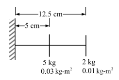
Figure 8.27 The overhung rotor with the shaft and disc properties