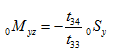
Boundary conditions are (i) y and φx at station 0 is zero, and (ii) at the free end shear force, Sy , and bending moment, Myz are zero. On substituting these boundary conditions in equation (j), we get
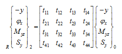 |
(k) |
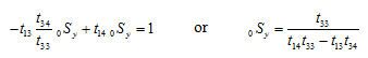
From the last two expressions of equation (k), we have
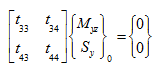 |
(l) |
Hence, on taking the determinant of equation (k) equal to zero, the frequency equation is
(m) |
which is,
![]()
From which transverse natural frequencies can be obtained by the by root searching numerical method described earlier by expressing the frequency equation as a function of the following form
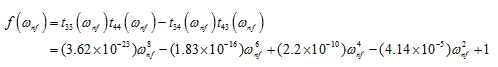 |
(n) |
Alternatively, through commercial software directly roots of equations can be obtained. Roots of this function are natural frequencies and are obtained as
![]()
For obtaining the mode shape, from the first two equations of (k), we have
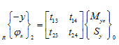 |
(o) |
For a given natural frequency, the first equation of equation (l) gives
 |
(p) |
By choosing Ry2 =1 as a reference value of the displacement, the first equation of equation (m) gives
(q) |
On substituting equation (p) into equation (q), the shear force at station 0 can be obtained as
 |
(r) |
The bending moment at station 0 can be obtained now from equation (p). Now, we have obtained the state vector at station 0 completely, and using the transformation matrices the state vectors at all other station can be obtained and are given as
(i) For first natural frequency : State vectors are given as
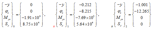
So that from above state vectors, we have
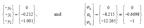
Figure 8.28 shows mode shape for y and φx corresponding to the first natural frequency.
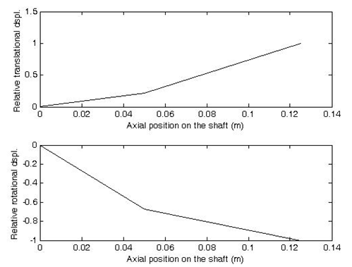
Fig. 8.28 Mode shapes corresponding to the first natural frequency (top) for the translational displacement and (bottom) for the rotational displacement