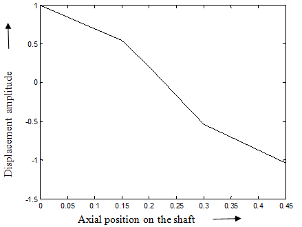
Fig. 8.33(b) The fundamental mode shape of rotational (slope) displacements
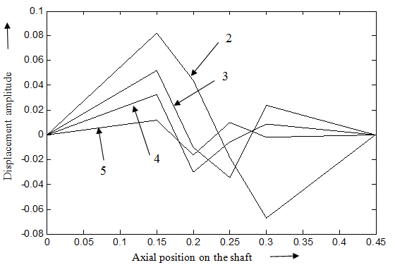
Fig. 8.33(c) Higher mode shapes (2nd to 5th) of translational displacements
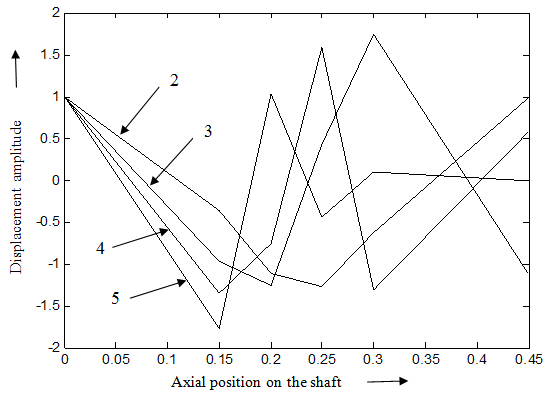
Fig. 8.33(d) Higher mode shapes (2nd to 5th) of rotational (slope) displacements
Answer .
Example 8.8 Obtain bending critical speeds of a rotor system as shown in Figure 8.34. Take the mass of the disc, m = 5 kg and its diametral mass moment of inertia, Id = 0.02 kg-m2 . The length of the shaft segments are a = 0.3 m and b = 0.7 m; and the diameter of the shaft is 0.01 m. Neglect the gyroscopic effects. E = 2.1 × 10¹¹ N/m2 .
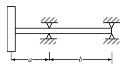
Figure 8.34 An overhang rotor system
Solution : Figure 8.35 shows the station numbering and free body diagram of various segments and supports.
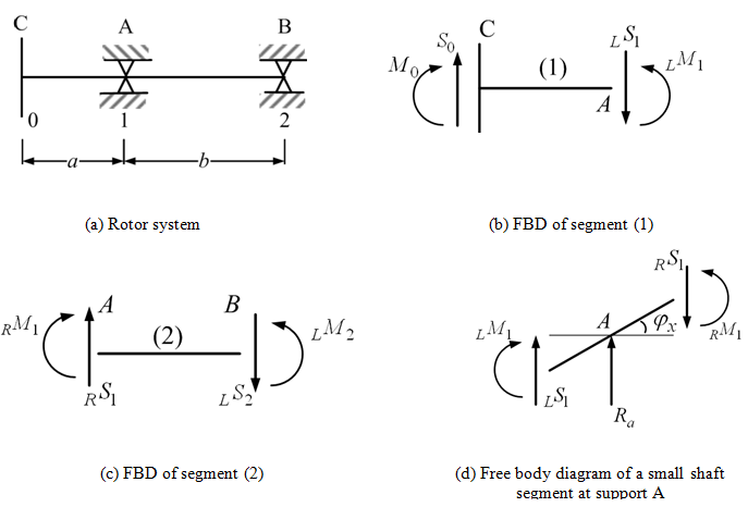
Figure 8.35 Free body diagrams of rotor segments