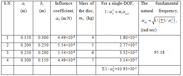
The system natural frequency from the Dunkerley 's formula is given as
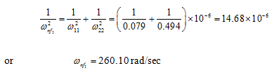
Using the TMM the value of the fundamental natural frequency was ωnf1 = 266.67 rad/sec. Hence, the Dunkerley 's formula estimates reasonably good estimate of the fundamental natural frequency, and it gives the lower bound.
Answer .
Example 8.11 Find fundamental transverse natural frequency of the rotor system shown in Figure 8.45. B1 and B2 are bearings, which provide simply supported end condition and D1 , D2 , D3 and D4 are rigid discs. The shaft is made of the steel with the Young's modulus E = 2.1 (10)11 N/m2 and uniform diameter d = 20 mm. Various shaft lengths are as follows: B1D1 = 150 mm, D1D2 = 50 mm, D2D3 = 50 mm, D3D4 = 50 mm and D4B2 = 150 mm. The mass of discs are: m1 = 4 kg, m2 = 5 kg, m3 = 6 kg and m4 = 7 kg. Consider the shaft as massless. Consider the discs as point masses.
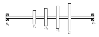
Figure 8.45 A multi-disc rotor system
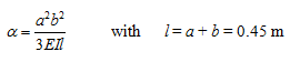
Solution : The influence coefficient for a simply support shaft with a disc is given as
 |
(a) |
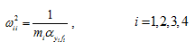
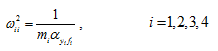
where l is the span of the shaft, and a and b are the disc position from the left and right bearings. The natural frequency of a single-DOF rotor system can be obtained as
 |
(b) |
We have d = 0.02 m, l = 0.45 m, EI = 1649.34 N-m2 . Hence, EIl 3 =450.89 N-m5 . Table 8.6 summarises the calculation of the fundamental natural frequency.
Table 8.6 Calculation procedure of the fundamental natural frequency using the Dunkerley 's formula
Answer .
Exercise 8.12 Find transverse natural frequencies and mode shapes of the rotor system shown in Figure 8.46. B is a fixed bearing, which provide fixed support end condition; and D1 , D2 , D3 and D4 are rigid discs. The shaft is made of the steel with the modulus of rigidity E = 2.1 (10)11 N/m2 and the uniform diameter d = 20 mm. Various shaft lengths are as follows: D1D2 = 50 mm, D2D3 = 50 mm, D3D4 = 50 mm and D4B2 = 150 mm. The mass of discs are: m1 = 4 kg, m2 = 5 kg, m3 = 6 kg and m4 = 7 kg. Consider the shaft as massless. Consider the disc as point masses, i.e., neglect the diametral and polar mass moment of inertia of all discs.
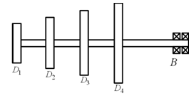
Figure 8.46 A multi-disc overhung rotor
Solution : The influence coefficient for a cantilever shaft with a disc at free end is given as
 |
(a) |
where L is the span of the shaft. The natural frequency of a single-DOF rotor system can be obtained as
 |
(b) |