 |
(h) |
 |
(i) |
 |
(j) |
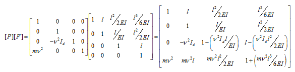
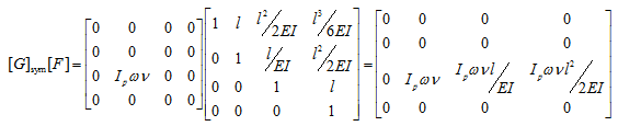
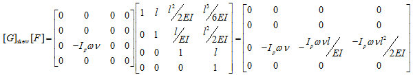
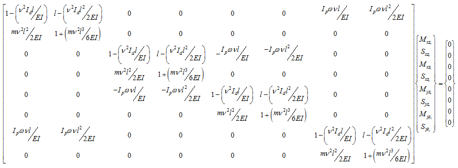
Boundary conditions for the present case are that all the translational and rotational displacements at station 0 are zero and all the moments and shear forces are zero at right of station 1. Hence, the state vector at station 0 and 1 have the following form
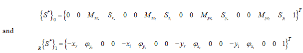
Following rows: 3, 4, 7, 8, 11, 12, 15, 16 will give the eigen value problem of the following form
 |
(k) |
We need to find for which the determinant of the above matrix is zero, i.e.
(l) |
It should be noted that the characteristic equation (or frequency equation) function f (v , ω) is function of whirl frequency, v, and the spin speed of the shaft, ω. Hence, whirl frequencies have to be obtained for a particular spin speed at a time. For different operating speed the solutions will help in plotting the Campbell diagram. Fig. 8.37 shows a flowchart of the solution algorithm to get the Campbell diagram from above frequency equation.
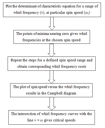
Fig. 8.37 Flowchart for a procedure to obtain the Campbell plot from frequency equation
Fig. 8.38 has been obtained for a particular spin speed of the rotor at 1000 rad/s. This plot gives four whirl frequencies corresponding to the one spin speed of the rotor. With decrease in the spin speed the first two roots (similarly, the third and fourth roots) would come closer (Fig. 8.39 For for ω = 500 rad/s). It should be noted that for ω = 0, in fact we would get only two roots (Fig. 8.40 For for ω = 0 rad/s). This is due to absence of gyroscopic couple when spin speed of the rotor is zero. On the other hand when the spin speed is increased separation between first two pairs (similarly, for pair of the third and fourth roots) of speed would be more (Fig. 8.41 For for ω = 1500 rad/s) due to increase in gyroscopic effect. Similar, four whirl frequencies can be obtained for different spin speeds one at a time. These whirl frequencies then could be plotted as a Campbell diagram as shown in Fig. 8.42.
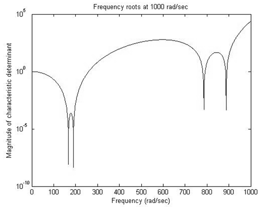
Fig. 8.38 A plot for variation of characteristic equation as function of the whirl frequency at a 1000 rad/s as spin speed of the rotor