Here α2j , …, αnj , where j =1, 2, …, n are another sets of constants and can be defined as described for α1i above. Hence, in general αij is defined as a displacement at i th station due to a unit external force at station j th and keeping all other external forces to zero. Equations (8.4) to (8.6) can be combined in a matrix form as
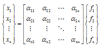 |
(8.7) |
It should be noted that due to the transverse force actually both the translational and rotational displacements take place, i.e., an elastic coupling exists between the translational and rotational displacements. We have already seen such coupling in Chapter 2 due to the bending of the shaft. In Chapter 4, we have seen the coupling between the horizontal and vertical plane translational motions (x and y) due to dynamic properties of fluid-film bearings. In Chapter 5, we have seen the coupling between the horizontal and vertical plane rotational motions (φx and φy) due to gyroscopic couples.
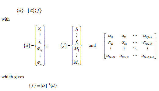
Similarly, a moment gives the rotational displacement as well as the translational displacement. The method can be extended to account for the rotational displacement (tilting), φy, of the disc, and for the application of the point moment, M, at various disc locations along the shaft. Then, equation (8.7) will take the following form
 |
(8.8)
(8.9)
(8.10) |
where αij , with i , j = 1, 2, …,2 n are influence coefficients. The first subscript defines the translational (or rotational ) displacement location and the second subscript defines the force (or moment) location. The analysis so far has referred only to static loads applied to the shaft. When the displacement of the disc is changing rapidly with time, the applied force has to overcome the disc inertia as well as to deform the shaft. It should be noted that the present analysis considers only a single plane deformation; however, similar analysis will be valid for another orthogonal plane. However, due to symmetrical nature of the shaft geometry the elastic coupling in two orthogonal planes will not exist. Coupling of rotational motions (φx and φy ) in two planes is also seen in Chapter 5 due to the gyroscopic couple .
8.1.2 The dynamic case : In Figure 8.2 free body diagrams of a disc and the shaft is shown. Let f1´ and M1´ be the external force and moment on the disc m1 whereas f1 and M1 are the reaction force and moment transmitted to the shaft (which is equal and opposite to the reaction force and moment of the shaft on the disc). From the force and moment balance of disc 1, we have
(8.11) |
where Id is the diametral mass moment of inertia the disc.
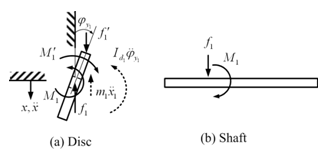
Figure 8.2 Free body diagrams of (a) a disc and (b) the shaft for a general motion
Similarly at other disc locations, we can write
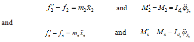 |
(8.12) (8.13) |
Substituting for ![]() from equations (8.11)-(8.13) and remembering that for the simple harmonic motion of discs
from equations (8.11)-(8.13) and remembering that for the simple harmonic motion of discs ![]() (when no external excitation is present then ω is the natural frequency of the system ωnf , and if there is an external excitation then it is equal to the excitation frequency, ω ), equation (8.8) gives
(when no external excitation is present then ω is the natural frequency of the system ωnf , and if there is an external excitation then it is equal to the excitation frequency, ω ), equation (8.8) gives
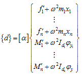 |
(8.14) |
which can be expanded as
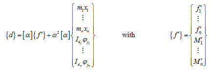 |
(8.15) |