TRANSVERSE VIBRATIONS-IV: MULTI-DOFs ROTOR SYSTEMS
Transverse vibrations have been considered previously in great detail for several single-mass rotor systems. The thin disc and long rigid rotors were considered with various complexities at supports; for example, the rigid disc mounted on flexible massless shaft with rigid bearings (e.g., the simply supported, overhung, etc.), the flexible bearings (anisotropic and cross-coupled stiffness and damping properties), and flexible foundations. Higher order effects of the gyroscopic moment on the rotor, for simple and most general cases of motion, was also described in detail. However, in the actual case, as we have seen in previous two chapters for torsional vibrations, the rotor system can have several masses (e.g., turbine blades, propellers, flywheels, gears, etc.) or distributed mass and stiffness properties, and multiple supports, and other such components like coupling, seals, etc. While dealing with torsional vibrations, we did consider multi-DOF rotor systems. Mainly four methods were dealt for multi-DOF systems, that is, the Newton's second law of motion (or the D'Alembert principle ), the Lagrange's equations, the transfer matrix method, and the finite element method. We will be extending the idea of these methods from torsional vibrations to transverse vibrations along with some additional methods, which are suitable for the analysis of multi-DOF rotor system transverse vibrations . In the present chapter, we will consider the analysis of multi-DOF rotor systems by the influence coefficient method, transfer matrix method, and Dunkerley's approximate method. The main focus of these methods would be to estimate the rotor system natural frequencies, mode shapes, and forced responses. The relative merit and demerit of these methods are discussed. The continuous system and finite element transverse vibration analysis of multi-DOF rotor systemswithout and with gyroscopic effects will be treated in subsequent chapters. Conventional methods of vibrations like the modal analysis, Rayleigh-Ritz method, weighted sum approach, collocation method, mechanical impedance (or receptance) method, dynamic stiffness method, etc. are not covered exclusively in the pres ent text book, since it is readily available elsewhere (Meirovitch, 1986; Thomson and Dahleh, 1998). However, the basic concepts of these we will be used directly whenever it will be required with proper references.
8.1 Influence Coefficient Method
In transverse vibrations due to coupling of the translational and rotational (tilting due to bending) displacements the analysis becomes more complex as compared to torsional vibrations. A force in a shaft can produce the translational as well as rotational displacements; similarly a moment can produce the rotational as well as translational displacements. Influence coefficients could be used to relate these parameters (the force, the moment, and the translational and rotational displacements) relatively easily. In the present section, the influence coefficient method is used to calculate natural frequencies and forced responses of rotating machines. Up to three-DOF rotor systems the hand calculation is feasible, however, for more than three-DOF the help of computer routines (e.g., MATLAB, Skylab, etc.) are necessary. The method is described for multi-DOF i.e., n number of discs mounted on a flexible massless shaft (Figure 8.1) and supported by rigid bearings; which can be extended for the multi-DOF rotor system with flexible multi-supports also.
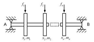
Figure 8.1 A multi-DOF rotor system mounted on rigid bearings
8.1.1 The static case: Let f 1 , f 2 , …, f n are static forces on discs 1, 2, …, n respectively, and x 1 , x 2 , …, x n are the corresponding shaft deflections at discs. The reference for the measurement of the shaft displacement is from the bearing axis (i.e., the undeformed position of the shaft) and the gravity effect is neglected. The system under consideration is a linear system. If a force f is applied to the disc of mass m 1 , then deflection of m 1 will be proportional to f , i.e.
(8.1) |
where α11 is a constant, which depends upon the elastic properties of the shaft and support conditions (e.g., simply supports, fixed supports, free supports, multi-supports, etc.). It should be noted that we will have deflections at other disc locations (i.e., 2, 3, …, n ) as well due to force at disc 1 due to the elastic coupling. Now the same force f is applied to the disc of mass m2 instead of mass m1 , then the deflection of m1 will still be proportional to the force, i.e.
(8.2) |
where, α12 is another constant (the first subscript represents displacement position and the second subscript represent the force location). In general we have α12 ≠ α11 . Similarly, if force f is applied to the disc of mass mn , then the deflection at m1 will be
(8.3) |
where, α1n is a constant. If forces f1 , f2 , ..., fn are applied at the locations of respective masses simultaneously, then the total deflection at m1 , will be summation of all the displacements obtained above by the use of superposition theorem , as
(8.4) |
In the equation, it has been assumed that displacements are small so that a linear relation exists between the force applied and corresponding displacement produced. Similarly, we can write displacement at other disc locations as
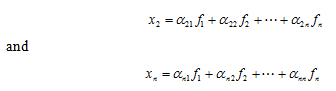 |
(8.5) (8.6) |