3.3.2 Theoretical estimation of dynamic coefficients of seals
In this chapter, basic governing equations to obtain dynamic coefficients of smooth annular turbulent seals (smooth seals) are presented. Dynamic coefficients are calculated from the approximate solution of the bulk flow theory for the configuration of the test rig. Effects of rotor speeds, seal dimensions, and operation conditions on these dynamic coefficients are also presented and discussed in detail.
Basic governing equations and approximate solution
In an annular seal, flows are usually turbulent because of high Reynolds numbers at which they operate. Black and his co-workers (Black 1969, Black and Jensen 1970) were the first to attempt to identify and model the rotor dynamics effects of turbulent annular seals using bulk flow models (on the similar lines to those of Reynolds lubrication equations). Bulk flow models employ velocity components, ![]() that are averaged over the clearance, where
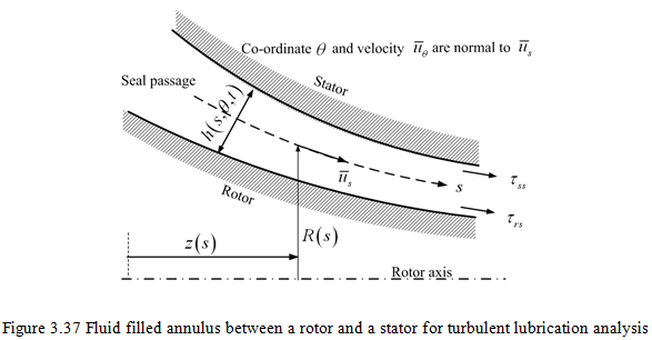
that are averaged over the clearance, where ![]() are the velocities in the directions and z and θ are the coordinates as shown Figure 3.37. Black and Jensen used several heuristic assumptions in their model, such as the assumption that
are the velocities in the directions and z and θ are the coordinates as shown Figure 3.37. Black and Jensen used several heuristic assumptions in their model, such as the assumption that ![]() where R is the radius of the seal and ω is the rotor speed. Moreover, their governing equations do not reduce to recognizable turbulent lubrication equations. These issues caused Childs (1983b) to publish a revised version of the bulk flow model and the present section will focus on Childs' model.
where R is the radius of the seal and ω is the rotor speed. Moreover, their governing equations do not reduce to recognizable turbulent lubrication equations. These issues caused Childs (1983b) to publish a revised version of the bulk flow model and the present section will focus on Childs' model.
The geometry of the seal annulus which is filled with fluid is sketched in Figure 3.37, and is described by coordinates of the meridian of the gap as given by z(s) and R(s), 0 < s < L, where the coordinate, s, is measured along that meridian and t is the time. The clearance is denoted by h(s, θ, t), where the unperturbed value of h is δ(s). Equations governing the bulk flow are averaged over the clearance. This leads to a continuity equation of the form
(3.108) |
where ![]() are velocities averaged over the local clearance.
are velocities averaged over the local clearance.
The axial and circumferential momentum equations are as follows
(3.109) |
and
(3.110) |
The approach used by Hirs (1973) is employed to determine the turbulent shear stresses, ![]() applied to the stator by the fluid in the s and θ directions respectively, which takes the following form
applied to the stator by the fluid in the s and θ directions respectively, which takes the following form
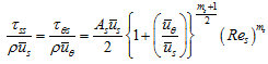 |
(3.111) |
and stresses, ![]() , applied to the rotor by the fluid in the s and θ directions respectively and are obtained as
, applied to the rotor by the fluid in the s and θ directions respectively and are obtained as
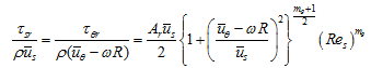 |
(3.112) |
where the local meridian Reynolds number is given as
(3.113) |
and constants As, Ar, ms, and mθ are chosen to fit the available data on turbulent shear stresses. Childs (1983a) uses typical values of these constant.
(3.114) |
Now the solution for the governing equation are presented and discussed in details.
Approximate dynamic coefficients of seals
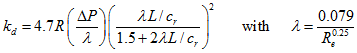
In the present subsection, the theoretical and computational analyses performed by various researchers have been compiled. Lomakin (1958) was the first to propose a theoretical model of a plain seal, which predicted that the axial pressure drop across the seal caused a radial stiffness, independent of shaft rotation. The radial direct stiffness (kd) is given by
 |
(3.115) |
where ΔP is the pressure drop, and R, L and cr are the radius, axial length and radial clearance of the seal, respectively. If the direct stiffness were the only effect of the plain seal, then its effect on critical speeds would be easily and accurately predictable. Black’s work (1969, 1971) provided the major initial impetus for the extensive research and the state of the art design information developed on this topic over the last four decades. Black developed the classical theory for turbulent annular seals, considering the axial fluid flow caused by a pressure drop along the seal, the rotational fluid flow as a consequence of the shaft rotation, and a relative motion of the seal between the rotor and housing. Black (1969, 1971) and Childs (1983a, b) formulated and extended Lomakin’s theory to be applicable to the rotor dynamic analysis of centrifugal pumps. Black, Childs, and others have shown, however, that kd increases with the shaft speed (at constant ΔP), and that the seal also produces cross-coupled stiffness (kc), direct and cross-coupled damping (cd and cc), and direct inertia coefficients (md). Moreover, the pressure drop will vary with the speed in most turbomachineries and the rotor dynamic effects are quite complex.
Clearances, pressures, and velocities are divided into mean components (subscript 0) that would pertain in the absence of whirl, and small linear perturbations (subscript 1) due to the eccentricity, ε, rotating at the whirl frequency, ω:
 |
(3.116) |