3.2 Hydrodynamic Fluid-Lubricated Journal Bearings
Hydrodynamic fluid-lubricated journal bearings have centuries of advances by empirical methods before there was awareness of the nature of the physical action by which a hydrodynamic lubricating firm is formed. In this computational age still the empirical methods has important place in journal bearing design. The built up of pressure in the film was experimentally reported independently by Tower (1883) in England and Petroff (1883) in Russia. Tower observed the development of hydrodynamic pressure first in partial journal bearings used in railway car wheel. The pressure generated is high enough to displace plugs used in the fluid holes. He, however, could not explain the physics behind the pressure generation. The first analytical investigation on losses in a hydrodynamic journal bearing was given by Petroff (1883). Petroff applied Newton’s law of viscous flow to a rotating concentric journal bearing and expressed the coefficient of fluid friction in terms of lubricant viscosity, speed and dimensions of journal bearings. This is given by
| (3.77) |
with
![]()
where µ is the coefficient of friction, , η is the coefficient of absolute viscosity of lubricant, N is the journal speed (rpm), q is the unit load, R is the journal radius, L is the length of journal and cr is the radial clearance. Equation (3.77) is called the Petroff’s equation. The equation has been found to a very good approximation for lightly loaded conditions. Three years later Reynolds (1986) explained the build up of pressure by viscous action in a convergent film. The physical understanding thus obtained assisted designers in choosing the position of lubricant supply and drain grooves in journal bearings.
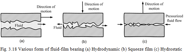
For a normal load to be supported by a bearing, positive-pressure profiles must be developed over the bearing length. Figure 3.18 illustrates three ways of developing positive pressure in fluid-lubricated bearings. For a positive pressure to be developed in a hydrodynamic bearing (Fig. 3.18a) the lubricant film thickness must be decreasing in the direction of motion. This action can be realized as motion of an inclined palm (e.g. 300 with direction of motion) over the surface of water. The palm will feel a upload thrust because of this wedge action between the palm and the water. In a squeeze film bearing (Fig. 3.18b) the squeeze action takes place because the bearing surfaces approach each other with the squeeze velocity. The squeeze mechanism of pressure generation provides a valuable cushioning effect when the bearing surfaces come closer to each other. Positive pressures develop only when the film thickness diminishes. This cushioning (squeeze) action can be felt when the palm is immerged in a bucket of water and then try to approach the wall (or bottom) of the bucket with certain velocity. In externally pressurized bearing, sometimes referred to as “a hydrostatic bearing” (Fig. 3.18c), the pressure drop across the bearing, supports the load. The load carrying capacity is independent of bearing motion and lubricant viscosity. There is no wear due to surface contact at the starting and the stopping of a rotor as there is with the slider bearing. This action can be felt if a thumb is pressed against the hole of a tap and then gradually the tap is opened. Because of the static pressure of the water the thumb will be lifted up (pushed away) from the hole of the tap.
There are other types of lubrications, i.e., the elasto-hydrodynamic and boundary lubrications. The elasto-hydrodynamic lubrication (EHL) is a form of hydrodynamic lubrication where elastic deformation of the lubricated surfaces becomes significant. The maximum pressure is typically between 0.5 to 3 GPa (for hydrodynamic lubrication it is of the order of 5 MPa); the minimum film thickness normally exceeds 0.1 mm (for hydrodynamic lubrication it is of the order of 1 mm). Rolling bearings and gears are some of the examples where EHL is exist (Hamrock, 1994). In boundary lubrication the contacting solids are not separated by the lubricant, fluid film effects are negligible and there is considerable asperity contact in the microscopic level. The contact lubrication mechanism is governed by the physical and chemical properties of thin surface films of molecular proportions. The properties of the bulk lubricant are of minor importance, and the friction coefficients are essentially independent of fluid viscosity. Boundary lubrication is usually not planned by the designer and characteristics are determined by the properties of the solids and the lubricant film at the common interfaces. However, it is better than the completely dry friction. The surface films vary in thickness from 1 to 10 nm. Hence, the coefficient of friction for the hydrodynamic bearing lubrication is of the order of 10-3, for the EHL it is 10-2, for the boundary lubrication it is 10-1 and for non-lubricated (or dry lubrication) it is 0.7 to 1.
3.2.1 Types of hydrodynamic bearings
Hydrodynamic journal (radial) bearing consist of a bearing bore that is normally circular and inside of which a circular section length of shaft (journal) is rotated. The journal diameter is usually 99.8 – 99.9% of that of the bore diameter of the bearing, and the clearance space between the two in partially filled by the lubricating fluid. At zero rotational speed, under a steady load, the journal touches at the bottom of the clearance space in the bearing bore. When the journal rotates, fluid is dragged along by the journal due to the fluid viscosity and a thin film of fluid is built up between the journal and bearing bore so that under normal operating conditions there is no surface-to-surface (or metal-to-metal) contact. The aim when designing for steady loads is to ensure that there is sufficient film clearance to take up the effects of the surface asperity and likely changes in load during the machine operation over a period of time.
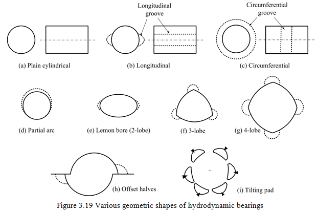
The most journal bearings operate at steady state eccentricity ratios (journal eccentricity/radial clearance) of about 0.6 – 0.7 so as to ensure that the bearing is not prone to self-excited vibrations. Hydrodynamic journal bearing can have a significant role on dynamics of rotors. The fluid film is equivalent to a complicated arrangement of the direct and cross coupled springs and dampers, and so influences the machine critical speeds and unbalance response. Moreover, bearing fluid film forces can cause rotor instability, which results in serious levels of self-excited vibration (e.g., fluid-film whirl/whip). The most common forms of the bore (solid line) and lubricant inlet ports (dotted line) of journal bearings are provided in Figure 3.19 and compared in Table 3.7.