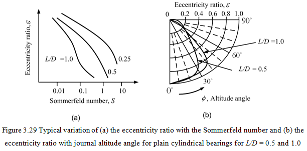
For bearing designed to carry vertical loads only (for example the gravity load) the relationship between eccentricity ratio ε and journal attitude angle, Φ, may be determined by investigating different values of Φ for a given value of ε until the value of Fh is found to be zero. For example, once we choose an arbitrary value of ε, Φ then corresponding film thickness can be obtained (since ε, Φ determines the position od the shaft with respect to the bearing bore). Using iterative procedure (or using all simultaneous solution procedure) the pressure distribution is obtained by putting negative pressure equal to zero, wherever it occurs. Resultant forces of the journal is obtained by using equations (3.88) and (3.89), for Fh = 0 and Fv = W . If the above force conditions are not satisfied, then different value of Φ could be chosen until the force conditions are satisfied up to the desired accuracy. When this process is completed it is found that, because the Reynolds equation is a continuous function, the final pressure distribution corresponds to the Reynolds boundary conditions with the constraint of ∂p/∂θ = 0 at the trailing edge of the lubricant film automatically catered for. Above procedure can be repeated for different value of ε to get relationship between of ε-Φ for a particular bearing at different operating conditions. This trial and error method enables corresponding value of ε, Φ , and Sommerfeld number S to be found. A typical steady-state journal loci for plain cylindrical bearings and their relationship with the Sommerfeld number are shown in Figure 3.29. For details readers are referred to book by Hamrock (1994).
3.2.6 Friction force and lubricant flow rate
Friction forces due to the shearing of the fluid film dissipate the heat energy in fluid film bearings. From the basic fluid mechanics the shear stress at some point in a fluid film is given by
| (3.90) |
where r is in film thickness direction, μ is fluid dynamics viscosity, and du/dr is velocity gradient across the fluid-film. In a hydrodynamic the velocity gradient term arises partly from the variation in pressure around the journal causing lubricant flow and partly as result of the journal rotation dragging lubricant around the clearance space. Thus, for a point at the journal surface, equation (3.90) becomes
| (3.91) |
The first term in the bracket is the pressure-induced term and the second term is the velocity-induced term. The total drag force, Fd, on the journal is then given by (s = Rdθ)
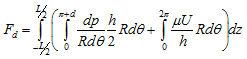 |
(3.92) |
where pressure-induced component is assumed to be present only when the lubricant pressure is positive, i.e. over the region ![]() The velocity-induced component is present wherever there is lubricant, for example all around the clearance space (with reasonable approximation). It is possible to develop closed-form expressions for the integral in equation (3.92) in the case of the infinitely long and infinitely short bearings (Pinkus and Sternlicht, 1961, also see previous section). In the case of finite bearings the integration may be carried out numerically and expressed as
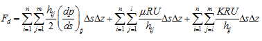
The velocity-induced component is present wherever there is lubricant, for example all around the clearance space (with reasonable approximation). It is possible to develop closed-form expressions for the integral in equation (3.92) in the case of the infinitely long and infinitely short bearings (Pinkus and Sternlicht, 1961, also see previous section). In the case of finite bearings the integration may be carried out numerically and expressed as
 |
(3.93) |
where l is the node corresponding to the edge of the pressurized section of the lubricant film (circumferential node position). Equation (3.93) is a slight variation of equation (3.92) in that the last term (3.93) of now allows for the breakup of the lubricant film, where K is a constant whose value is less than unity. The magnitude of K may be determined empirically. This feature of real lubricant film is not allowed for in equation (3.92).
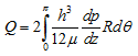
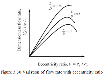
In case of both the infinitely short and infinitely long bearing there is a lubricant pressure variation in the axial direction for ![]() causing a flow of lubricant out of the ends of the bearing. This flow rate, allowing for both ends of the bearing, is given by basic fluid mechanics theory as
causing a flow of lubricant out of the ends of the bearing. This flow rate, allowing for both ends of the bearing, is given by basic fluid mechanics theory as
 |
(3.94) |
For the finite bearing, using a trapezium rule for integration for the finite difference mesh shown in Figure 3.28, we have
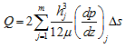 |
(3.95) |
A typical variation of the flow rate is shown in Figure 3.30.
3.2.8 Dynamic characteristics of fluid-film bearings
The center of journal of a hydrodynamic bearing takes a static equilibrium position for a particular speed when it is subjected to a static load (e.g., the weight of the journal). However, when a dynamic load (e.g., unbalance) is applied to the bearing the journal is caused to oscillate about the static equilibrium position. The journal is subjected to the effective stiffness and damping forces associated with this flexibility of the lubricating film. These forces have a significant effect on the system whirl natural frequencies, critical speeds, forced responses, and the system stability. This demands to evaluate the bearing dynamic characteristics at the design stage itself. This is obtained by providing some small displacements (perturbations) dx and dy of the journal away from its static equilibrium position, in the horizontal and vertical directions, respectively. The journal center is also assumed to possess velocities ![]() in the horizontal and vertical directions, respectively (whereas under the action of only a steady load its velocity would be zero). The effects of these perturbations on the state of the journal on the lubricant film forces are then calculated. When there is no dynamic load on the journal, the lubricant steady-state film forces in the horizontal and vertical directions could be expressed as functions of the journal positions, x and y, and velocities,
in the horizontal and vertical directions, respectively (whereas under the action of only a steady load its velocity would be zero). The effects of these perturbations on the state of the journal on the lubricant film forces are then calculated. When there is no dynamic load on the journal, the lubricant steady-state film forces in the horizontal and vertical directions could be expressed as functions of the journal positions, x and y, and velocities, ![]() , away from the bearing center; that is
, away from the bearing center; that is
| (3.96) |
where ![]() are both zero. When there are changes in these displacements and velocities, the new values of lubricant film forces will be Fx + dFx and Fy +dFy, respectively. These forces may also be expressed using equation (3.96) as a four-variable Taylor series, neglecting higher order small terms, as
are both zero. When there are changes in these displacements and velocities, the new values of lubricant film forces will be Fx + dFx and Fy +dFy, respectively. These forces may also be expressed using equation (3.96) as a four-variable Taylor series, neglecting higher order small terms, as
| (3.97) |
and
| (3.98) |