3.2.4 Short and long hydrodynamic radial bearings
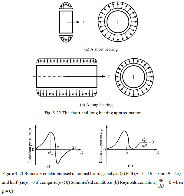
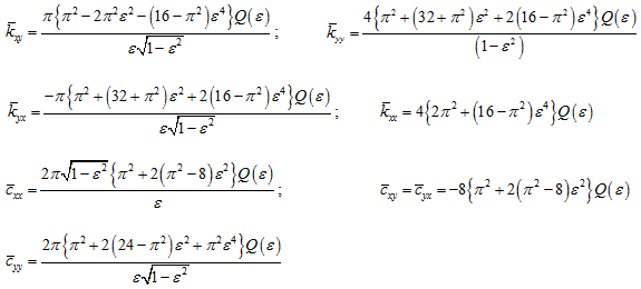
Equation (3.79) describes the variation of lubricant pressure in both the axial (i.e., z) and circumferential (i.e., s) directions. An approximate solution (closed form) may be obtained by using the short bearing (Ocvirk, 1952) approximation. In this case the pressure variation in the circumferential direction (i.e., ∂p/∂s) is assumed to be negligible compared with that in the axial direction (i.e., ∂p/∂z) and so that ∂p/∂s is set to zero (Fig. 3.22a). This approximation also enables closed-form solution of equation (3.79) to be obtained, provided that appropriate boundary conditions (Figure 3.23) are selected to enable evolution of the constants of integration (Cameron, 1981; Pinkus and Sternlicht, 1961 and Rao, 1993).
The conventional boundary condition for the hydrodynamic bearing film is p = 0, with p measured relative to atmospheric pressure. The position of the boundary, where this condition holds, is known when the film starts at an fluid-supply groove and when it ends at the side of the bearing or at an fluid-drain groove. An additional assumption is required to determine the position at which the hydrodynamic bearing film starts or terminates when this is not fixed by a supply or drain groove. A widely used assumption takes the hydrodynamic bearing film as starting at θ = 0, the position of maximum clearance (Fig. 3.20a). This assumption is convenient for calculation, but is not fulfilled in practice unless there is sufficient fluid available to form a continuous film at that position. Calculation show, however, that if the film is assumed to start at a small angle after the position of maximum clearance the overall characteristics of the bearings are only slightly affected at normal operating attitudes. The additional condition, which is taken in the conventional calculation for defining the position at which the hydrodynamic bearing film terminates within clearance, is ∂p/∂θ = 0. This condition is justified by the following argument which applies when p = 0 holds at the boundary – if ∂p/∂θ had been positive there could have been a longer film with positive pressure; if ∂p/∂θ had been negative there would have been negative pressure in the film.
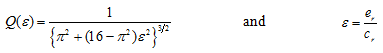
The eight linearized stiffness and damping coefficients depend on the steady state operating conditions of the journal, and in particular upon the angular speed. For the short bearing, the dimensionless bearing stiffness and damping coefficients, ![]() and i, j = x, y, as a function of the steady eccentricity ratio, ε, of the bearing are given as (Smith, 1969)
and i, j = x, y, as a function of the steady eccentricity ratio, ε, of the bearing are given as (Smith, 1969)
 |
(3.81) |
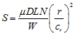
with
 |
(3.82) |
where er is the journal eccentricity and cr is the radial clearance. To determine stiffness and damping coefficients of a short bearing, the Sommerfeld number or bearing characteristic number
 |
(3.83) |
is first determined, where W is the load on the bearing, r is the bearing radius, D is the journal diameter, L is the length of bearing, µ is the viscosity of lubricant at operating temperature, ![]() the angular speed of journal, and n is the number of revolutions per seconds. We can then determine the eccentricity ratio under steady state operating conditions by
the angular speed of journal, and n is the number of revolutions per seconds. We can then determine the eccentricity ratio under steady state operating conditions by
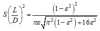 |
(3.84) |
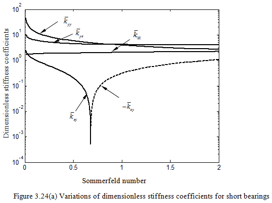
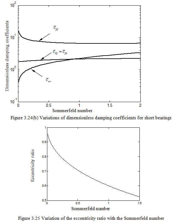
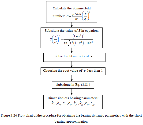
Variations of the dimensionless stiffness and damping coefficients with Sommerfeld number for the case of short bearing approximation is shown in Figure 3.24 (a) and (b). Variation of the eccentricity ratio with the Sommerfeld number is given in Figure 3.25. Algorithm for finding dimensionless bearing dynamic parameters from the Sommerfeld number is given in Figure 3.26.
For the “long bearing” approximation (Hamrock, 1994), the pressure variation in the axial direction is assumed to be negligible compared with that in the circumferential direction and so ∂p/∂z is set to zero (Fig. 3.22b).