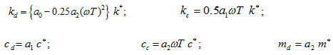
These expressions are substituted into governing equations (3.108)-(3.110) to yield a set of equations for mean flow quantities and a second set of equations for perturbation quantities; terms which are of quadratic or higher order in ε are neglected. Resulting zeroth-order equations define the leakage and the circumferential velocity development, and are solved by numerical methods. From the first order equations, the time and θ dependency is eliminated to obtain the pressure distribution solution. It is then integrated along and around the seal clearance to yield reaction force components. From rotor dynamic force components, following rotor dynamic coefficients and constants are obtained (Childs, 1983).
 |
(3.117) |
with
 |
(3.118)
(3.119)
(3.120)
(3.121)
(3.122) |
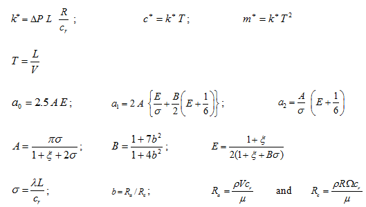
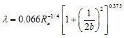
where k, m, and c are the stiffness, mass and damping coefficients respectively, k*, c* and m* are reference values of corresponding quantities, a0, a1 and a2 are dimensionless coefficients, ω is the speed of the rotor, T is the transit time as given in equation (3.119), L is the length of the seal, V is the average axial stream velocity, ξ is the entrance loss coefficient, ρ is the fluid density, λ is the friction coefficient, R is the radius of the seal, cr is the clearance of the seal, and ΔP is the difference between pressures at the inlet and the exit of the seal. Subscripts d and c represent the direct and cross-coupled terms, respectively. Ra is the Reynolds number for the axial flow, and Rc is the Reynolds number for the circumferential flow for smooth annulus seals. Dimensional coefficients are thus functions of ξ, σ, and b. To determine coefficients a0, a1 and a2 another coefficients σ and b are required for the frequently occurring value of ξ = 0.5. From Childs (1983a), we have
 |
(3.123) |
To calculate λ, the average velocity V is inserted into equation (3.122). The expression for V can be obtained from the fundamental relationship for the pressure difference,
(3.124) |
So, the average axial stream velocity can be expressed as
(3.125) |
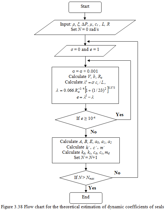
Since the desired value of λ is also function of V and thereby σ, hence, it is best obtained iteratively. From σ the dynamic coefficients can be obtained for different speed ω. Figure 3.38 shows an algorithm for the solution of dynamic coefficients of seals using equations (3.117) to (3.125).
Numerical Simulation
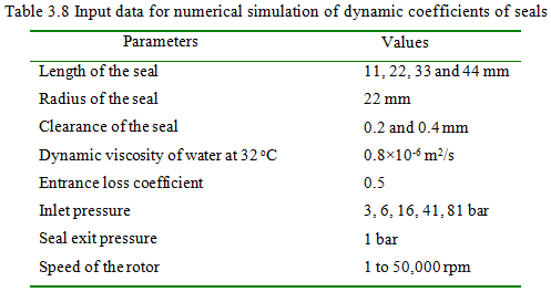
In this subsection, numerical results of dynamic coefficients of seals are presented for the rotor speed up to 50,000 rpm. The input data are for the present numerical simulation is given in Table 3.8
Seals dynamic coefficients are dependent on speeds, seal dimensions, and pressure differences. The stiffness (kd and kc), damping (cd and cc), and mass (md) coefficients are presented for various speeds (ω), pressure differences (ΔP), and ratios (L/D).
Figures 3.39 to 3.51 show the variation of the direct and cross-coupled stiffness and damping coefficients, and direct inertia coefficients with respect to the speed up to 50000 rpm, for different values of clearances (0.2 and 0.4 mm), L/D ratios (0.25, 0.50, 0.75 and 1.00), and pressure differences (2, 5, 15, 40 and 80 bar). The effect of these variables on seal dynamic coefficients are discussed in detail in following sections.