Example 3.3 Determine the non-linear stiffness of a bearing having the following specifications: Ball bearing type: SKF 6200, number of balls = 6, ball diameter = 6 mm, bore diameter = 10 mm, outer diameter = 30 mm, pitch diameter = 20 mm, inner groove radius = 3.09 mm, outer groove radius = 3.09 mm, allowable pre-load = 0 - 2 μm and rotor mass per bearing = 0.41 kg.
Solution: The value of ![]() for the bearing with given specifications from Example 3.2 is estimated as 2.844 X 10⁵ N/mm1.5. Let us take a general form of the non-linear restoring force as
for the bearing with given specifications from Example 3.2 is estimated as 2.844 X 10⁵ N/mm1.5. Let us take a general form of the non-linear restoring force as
(a) |
where G can be a polynomial in x, and kL and kNL are respectively the linear and non-linear stiffness contribution parameters. For the present problem G(x) is taken as cubic in x, so that
(b) |
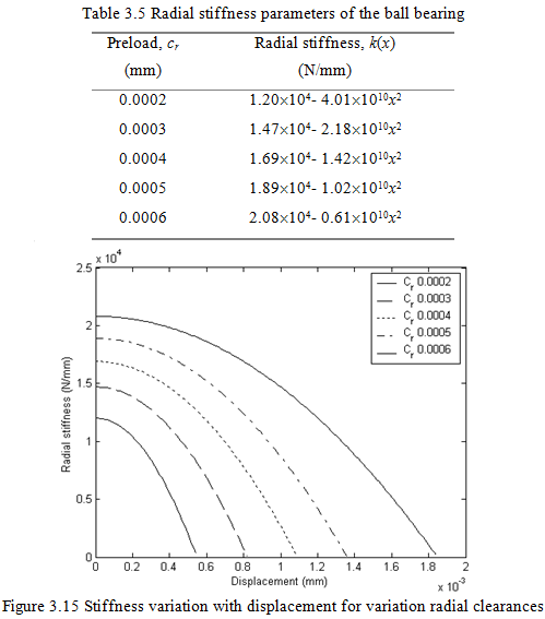
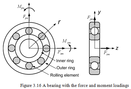
Based on the method discussed in previous section, the stiffness of the bearing is plotted in Figure 3.15 as a function of the radial deformation, x, for various allowable preload values cr. It is to be noted that the stiffness calculations are based on formulations, which analyses the bearing in isolation of the shaft. The expressions for the stiffness in Table 3.5 have been obtained by curve fitting the stiffness values obtained from equation (3.45), through a quadratic in x (equation b).
3.1.3 Linear stiffness determination under combined loadings*:
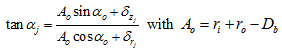
Stiffness characteristics of rolling element bearings are studied under combined loading (see Figure 3.16), i.e., under the action of the radial and axial forces and the moment. Hence, there will be the radial, axial, and angular displacements. All the displacements are coupled assumed to be coupled, i.e., they will depend upon the combined effect of all the forces and moments acting on the bearing. The stiffness matrix obtained is of size 5 ´ 5. To obtain displacements a set of five non-linear equilibrium equations are solved for a given loading conditions (Lim and Singh, 1990). Apart from these equilibrium equations the geometrical and deformation equations would also be needed.
* In an advanced topic and can be omitted, if required.
The load-deflection relationship for a single rolling element can be expressed as
(3.61) |
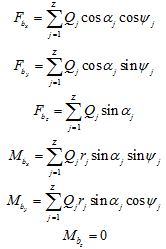
where Qj is the normal load on the rolling element and ![]() is the effective load-deflection constant for the contact of a rolling element with the inner and outer races. The actual contact angle after loading is given as
is the effective load-deflection constant for the contact of a rolling element with the inner and outer races. The actual contact angle after loading is given as
 |
(3.62) |
Now the force and moment balance equations can be obtained as follows
 |
(3.63) (3.64) (3.65)
(3.66) (3.67) (3.68) |
Stiffness coefficients can be obtained by differentiating the force {f}b with respect to the displacement {q}b.
(3.69) |
This will give a 5X5 stiffness matrix. Displacements can be obtained by solving equations (3.62) to (3.68) along with certain geometrical constraints. Then the stiffness matrix can be obtained by equation (3.69). The details can be seen in Lim and Singh (1990).