In previous chapter rotor systems were analyzed for simple cases by taking the shaft as flexible and the bearing as rigid. However, in the real case bearings do provide flexibility to the rotor system. Depending upon the type of bearing or other similar machine elements (e.g., dampers, seals, etc.), these provide the stiffness and/or the damping to the rotor system (or sometimes added-mass or inertia terms). In the present chapter, procedure to theoretically obtain these dynamic properties of the support system will be explained. First, rolling element bearings are introduced and classified, and its relationship between the load and the deformation are derived from the basic Hertzian contact theory. From the load-deformation relation then stiffness of the rolling element bearing is obtained. Hydrodynamic radial bearings are introduced and classified according to the shape of the bore and lubricant groove positions. For obtaining the stiffness and damping coefficients of the hydrodynamic radial bearing a procedure is described by using the basic Reynolds equation. For a simple case of the short bearing assumption a closed form results are presented. Next, dynamic seals are introduced and classified based on various categories. Based on bulk flow models governing equations are presented and for a simple case the dynamic parameters are obtained and analyzed for various operating parameters. Finally, basics of squeeze-film dampers are introduced and relevant rotordynamic parameters are presented. The main aim of the present chapter is not give exhaustive coverage of bearings, seals, and dampers; since each of them is a subject in itself. The basic premise of the present chapter is to acquaint a reader regarding rotor-dynamic parameters of these machine elements so that if needed a detailed analysis could be performed through the available text books on these topics. Hydrostatic bearings, gas bearings, foil bearings, etc. have not been dealt with here, however, these do impart similar rotor-dynamic characteristics to the rotor systems.
All rotating machineries are supported by bearings and fitted with seals and dampers. The bearings clearly constitute a vital component in any turbo-machine and a good understanding of their dynamic properties is a pre-requisite to the prediction of the machine’s behaviour. The influence of bearings on the performance of rotor-bearing systems has been recognised for many years. One of the earliest attempts to model a journal bearing was reported by Stodola (1925) and Hummel (1926). They represented the fluid-film as a simple spring support, but their model was incapable of accounting for the observed finite amplitude of oscillation of a shaft operating at a critical speed. Concurrently, Newkirk (1924) and Newkirk and Taylor (1925) described the phenomenon of bearing induced instability, which he called oil whip, and it soon occurred to several investigators that the problem of rotor stability could be related to the properties of the rotor dynamic parameters i.e. RDPs (the rotor dynamic parameters (or dynamic parameters) are also known as: bearings/seals force (or moment) coefficients; added-mass, damping and stiffness coefficients; linearized rotor dynamic parameters; dynamic impedances, etc.).
Seals are mainly used to reduce the leakage of working and lubricating fluids through the interface between machine moving parts. Some leakage is inevitable, and it results in axial fluid velocities though the seal in the direction of the pressure drop. The present day requirement of critical sealing applications have a diverse range of operating condition requirements such as (i) cryogenic temperature, (ii) hard vacuum, (iii) ultra-clean systems, (iv) leakage control to 10-12 cc/sec, (v) pressures over 100 bar, (vi) temperatures exceeding 800°C, (vii) hard-to-handle liquids and gases, (viii) high pressure pulsations, and (ix) rotor speeds as high as 105 rpm. These extreme conditions of seals are challenging tasks in the present space-age for the aviation and aerospace industries. The importance of calculations of RDPs of seals arose in the late 1970s in regard to vibration problems related to high-pressure oxygen turbo-pump of the space shuttle main engine. Compressors used in many industries also had the instability problems within the operating speed range. Seals in high-speed operations of turbo-machines leads to instability. The main factor, which governs the instability, is RDPs of seals. RDPs of seals are greatly dependent on many physical and mechanical parameters such as lubricant and working fluid temperatures, pressure drop, seal clearances, surface roughness and patterns, rotor speeds, eccentricity, and misalignments.
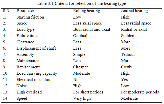
Designers should know the types of bearings, dampers, and seals that could be used, and performance characteristics associated with each of them. The main aim will be towards the operation of bearings, dampers, and seals under the action of dynamic loads, in particular the RDPs of different types of bearings, dampers, and seals are discussed. These characteristics have a major influence on the overall system dynamics. Bearing types are (i) rolling element bearings (ii) fluid film hydrodynamic bearings (iii) gas bearings (iv) squeeze film bearings/dampers and (v) hydrostatic bearings. Dynamic seals can be classified as (i) plain seals (ii) roughened seals (iii) contact seals, and (iv) brush seals. Table 3.1 compares some of the criterion of selection between the rolling and journal bearings, which find frequent application in rotating machinery. Now rolling element bearings, fluid-film bearings, seals, and dampers will be introduced one by one.
3.1 Rolling Element Bearings
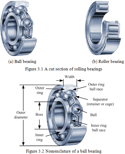
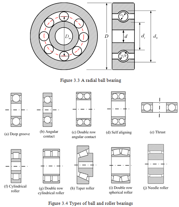
Rolling element bearings or simply rolling bearings are the most common type of bearings and it has around 94% usage in industry (around 5.5% for hydrodynamic/static fluid-film journal bearings, and less than 0.5% for other bearings including active bearings). It requires less boundary dimensions and can transmit heavy and variable loads of various forms. It can easily be installed, serviced and replaced. Figure 3.1 shows a cut section of the ball and roller bearings. The nomenclature and various basic geometries of a most simple deep groove ball bearing are shown in Figures 3.2 and 3.3, respectively. Various symbols represent: d is the bearing bore diameter, D is the bearing outer diameter, Db is the ball diameter, ri is the inner raceway curvature radius, and ro is the outer raceway curvature radius, di is the inner ring outer diameter, and do is the outer ring inner diameter. Various types of rolling element bearings (refer Figure 3.4) are: deep groove ball bearings, self-aligning ball bearings, angular contact ball bearings, split type angular contact ball bearings, cylindrical roller bearings, spherical roller bearings, tapered roller bearings, needle roller bearings, thrust ball/roller bearings, and linear re-circulating ball bearings. These bearings are selected on the basis of the magnitude and direction of the loading and speeds. Table 3.2 summarizes various bearing types available, together with their relative merits, common applications, and friction coefficients. For rotor dynamics point of view our main aim of the present section is to study bearing elastic deformation, and the evaluation of the linear and non-linear bearing stiffness parameters. The bearing stiffness plays an important role in the determination of the overall rotor bearing system dynamic characteristics, e.g., natural frequencies, critical speeds, unbalance/transient response, and stability analyses. These stiffness parameters are not usually documented in manufacturer’s selection catalogues. Damping in rolling element bearings is very small (i.e., 0.001-0.005, see Table 3.2), however, it may be significant in the case lubricant is trapped between the outer ring and bearing housing, due to the squeeze-film action.