Example 3.1 Obtain the load zone angle of a rolling bearing for the following cases (i) cr = xm (ii) cr = -xm (iii) cr = 0.5xm (iv) cr= - 0.5xm; where xm is the displacement of inner ring from the concentric position andcr is the radial clearance. Draw load zones for each case.
Answer:
Case I: We have cr = xm . Thus, φL is the load zone angle = cos(cr / xm) = cos-1(1) = 0°. Hence, none of the bearing element is loaded.
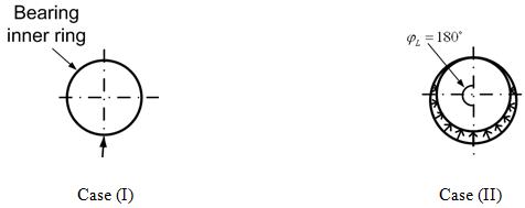
Case II: We have cr = -xm. Thus, φL = cos-1(cr / xm)= cos-1(-1) = 180°.Hence, all rolling elements will take part in the load sharing.
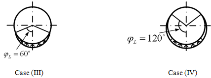
Case III: We have cr = 0.5xm. Thus, φL = cos-1(cr / xm) = cos-1(0.5) = 60°. Hence, Very less number of rolling elements will take part in load sharing.
Case IV: We have cr = -0.5xm . Thus, φL = cos-1(cr / xm) = cos-1(-0.5) = 120°. Hence, Sufficient number of rolling elements will take part in the load sharing.
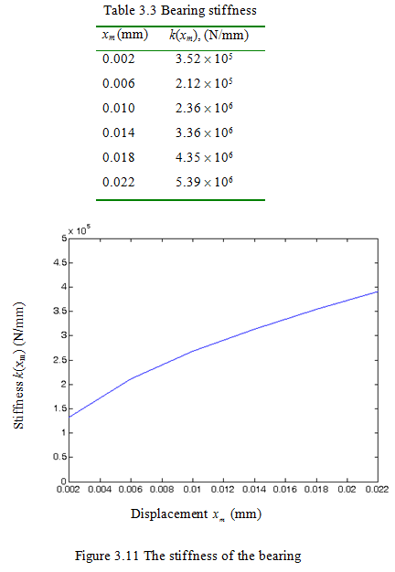
Example 3.2 The specification of a SKF 7218 angular contact ball bearing are as follows: Inner and outer grove curvature radius = 11.64 mm, Inner raceway diameter = 102.92 mm outer raceway diameter 147.9 mm, bore diameter = 90.0 mm, outer diameter = 160.0 mm, ball diameter = 22.25 mm, number of balls = 16 and preload = 0.6 μm. Plot bearing radial stiffness versus elastic radial deformation. For plotting purpose take six points i.e. take elastic deformations: 0.002 mm, 0.006 mm, 0.01 mm, 0.014 mm, 0.018 mm and 0.022 mm.
Answer: From equation (3.26), for the stiffness of the ball bearing, we have
![]()
where Z is the number of balls = 16 ; (-cr) = preload = 0.6 μm = 0.6 X 10⁻³ mm. From equation (3.8), we have
![]()
with
![]()
where r = radius of curvature of raceway = 11.64 mm and Db = diameter of ball = 22.25 mm. Hence,
![]()
Hence, the stiffness can be obtained as
![]()
Figure 3.11 shows the variation of the stiffness with displacement due to static loads. The stiffness values for various bearing static displacements are also provided in Table 3.3.
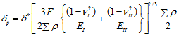
3.1.2 Nonlinear stiffness of rolling bearings*: Alternately, more accurate determination of the stiffness of rolling contact bearings can be performed as follows (Harris, 2000). From theory of elasticity for two bodies in contact (Timoshenko and Goodier, 1950), we have
* It is an advance topic and can be omitted, if required.
 |
(3.28) |
with
 |
(3.29) |
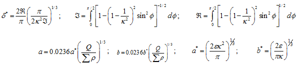
where, δp is the deformation at the contact, F refers to normal force between contacting bodies, subscripts I and II refer to the first and second contacting bodies, E refers to the Young’s modulus, n refers to the Poisson’s ratio, the elliptical eccentricity parameter k = a/b, a and b are the semi-major and semi-minor axes of the elliptical contact area for the point contact, a* and b* are the dimensionless semi-major and semi-minor axes respectively, Σρ is the curvature sum, and δ* is the dimensionless contact deformation. Equation (3.28) can be rearranged as
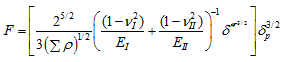 |
(3.30) |
On comparing equations (3.30) and (3.3), we have
 |
(3.31) |
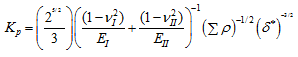
where p refers to the point contact (either at the inner or outer raceway). For the steel ball and the steel raceway contact, we have
| (3.32) |
which can be written for the inner and outer ring contacts, as
| (3.33) |
with
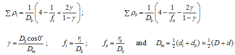 |
(3.34)
(3.35) |
where Db is the ball diameter, Dm is the pitch diameter, ![]() is the contact angle, di and do are the inner and outer ring raceway contact diameter respectively; and ri and ro are the inner and outer raceway groove radii, respectively. We have
is the contact angle, di and do are the inner and outer ring raceway contact diameter respectively; and ri and ro are the inner and outer raceway groove radii, respectively. We have
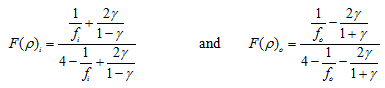 |
(3.36) |
where F(ρ) is curvature difference. The plot of δ* as function of F(ρ) is shown in Figure 3.12 and listed in Table 3.4.