As an illustration, the analysis of the above case has done for a deep groove ball bearing having following parameters: the load-deflection exponent n = 3/2, the load-deflection constant ![]() = 8.5 X 10⁹ N/mm1.5, the number of rolling elements Z = 12, the diametral clearance Pd = 0.00005 mm, the pitch diameter Dm = 19.65 mm and A0 = 0.05 mm.
= 8.5 X 10⁹ N/mm1.5, the number of rolling elements Z = 12, the diametral clearance Pd = 0.00005 mm, the pitch diameter Dm = 19.65 mm and A0 = 0.05 mm.
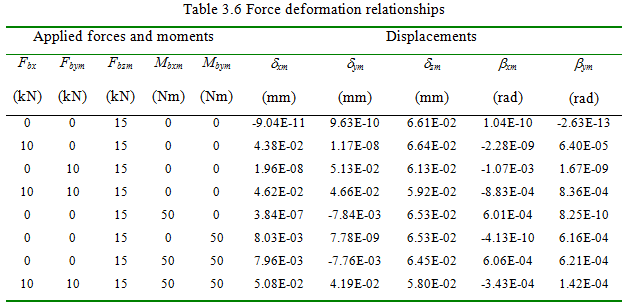
Table 3.6 summaries the analysis for various loading conditions. When only an axial load is applied, the axial displacement is found to be significant, other displacements are negligible. Along with the axial, if some radial load is applied, the radial displacement is found to vary significantly and angular displacements are very small. Now if in addition to axial load, some moment is applied, considerable amount of the angular displacement is observed. For combined loading all displacements are found to be significant. These load-deflection relations can be used to obtain the stiffness coefficients, by giving small perturbations to these forces (or moments) and estimating the change in the deflections. Now, the calculation of stiffness for a simple loading of pure radial case is considered, subsequently. However, now we will be adding the effect of centrifugal forces in rolling elements.
3.1.4 Radial stiffness at high-speed conditions*
* It is an advanced topic and can be omitted, if required.
In analyses of previous sections only static load was applied to the rolling bearings, and the linear stiffness was obtained at that static deformation by giving a small perturbation around it. In high-speed operations, rolling element centrifugal forces can be significantly large compared to the applied static forces to the bearing. Increase of loading due to centrifugal force causes larger contact deformation at the outer raceway, which can be compared with the effect of increasing the clearance on displacement characteristics of the rolling element. High speed also affects the lubrication characteristics and thereby the friction in bearings. This will have an influence on bearing internal speeds, which in turn alters the rolling element internal loading i.e. centrifugal forces and gyroscopic moments.
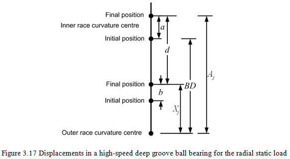
Figure 3.17 shows the displacement of a ball bearing due to a radial loading. Under no load centers of raceway groove curvatures are separated by a distance BDb, i.e. (fo + fi -1)Db, where fo = ro/Db and fi = rii/Db. Distances a is given by δr cosψj, b =δoj and d = (fi - 0.5)Db + δij, where δr is the radial displacement of the bearing, δij and δoj are contact deformations at the inner and outer raceways, respectively, of jth rolling element at azimuth angle of ψj.
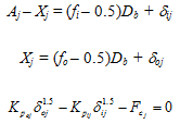
Under an applied static load, the distance between centres of groove curvature radii will increase by the amount of contact deformations (δi + δo). The line of action between centres is collinear with the line joining fixed outer raceway groove curvature centre with the initial position of the inner raceway curvature centre. Even when the centrifugal force acts on the ball, since the inner and outer raceway contact angles are similar, the line of action remains collinear. It is assumed that the outer raceway groove curvature centre remains fixed in space and the inner raceway groove curvature centre moves relative to that fixed centre. The distance between the fixed outer raceway groove curvature centre and the final position of the ball centre at any ball location is given by
(3.70) |
Similarly, the distance between the final position of inner raceway groove curvature centre and the final position of ball centre at any ball location is given by
(3.71) |
where δoj and δij are normal contact deformations at the outer and inner raceway contacts. As evident from Figure 3.17,
 |
(3.72) (3.73) (3.74) |
Equations (3.72)-(3.74) can be solved simultaneously for Xj, δij, δoj at each ball angular location for a given assumed value of δr using the Newton-Raphson numerical method. The radial displacement δr can be obtained by the following equation, which should be satisfied for the entire bearing.
(3.75) |
where Fr is the radial static load and Qij is the normal load at the inner raceway. The linearized stiffness can be obtained by giving small perturbation about the equilibrium position of the ball bearing, and then obtaining the force required to give that perturbation. Let the perturbation given is ±(dδr)about the mean equilibrium position. The stiffness is defined as follows
 |
(3.76) |
where ![]() is the force on the rolling bearing, when a +(dδr)perturbation is given about the mean position and
is the force on the rolling bearing, when a +(dδr)perturbation is given about the mean position and ![]() is the force on the rolling bearing for a perturbation of-(dδr) about the mean position. For detailed treatment readers are referred to books by Changsen (1991) and Harris (2001).
is the force on the rolling bearing for a perturbation of-(dδr) about the mean position. For detailed treatment readers are referred to books by Changsen (1991) and Harris (2001).