When the bearing inner ring is displaced from the concentric position by a distance xm with respect to the outer ring center, part of it consists of the radial clearance cr . The elastic deformation in the direction of applied radial load will be
| (3.12) |
and the elastic deformation of any rolling element at an azimuth angle, Ψ, as Figure 3.9(b), is given by
| (3.13) |
By setting deformation to zero in equation (3.13), the load zone, Ψl, can be obtained by
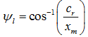 |
(3.14) |
From the equilibrium of ring (inner or outer), we have (Fig. 3.9)
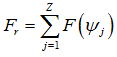 |
(3.15) |
where Z is the number of rolling elements. For a given bearing, with known angular positions of rolling elements (i.e., in general for analysis, rolling elements are arranged symmetrically to the loading such that one of the rolling element is just below the radial external load), ), a displacement of the inner ring xm is assumed and thus the resulting elastic deformation, δ(Ψ), at each rolling element is calculated from equation (3.13). Contact forces at each element may then be evaluated from equations (3.5) and (3.8). These are added as vectors to give the net radial forces, Fr, (i.e., equation (3.15)) applied to the bearing in order to produce the assumed displacement xm. In case there is a difference between the estimated net radial force and applied radial force, a new displacement is then chosen and above procedure is repeated until it converges up to the desired accuracy.
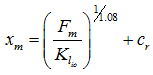
If the fraction of the net radial load applied that is transmitted through the rolling element directly in line with the applied load in known than the resulting inner ring displacement xm may be calculated directly, from equation (3.5) for the ball bearing, as
| (3.16) |
with
 |
(3.17) |
where Fm is the force on the rolling element directly in line with the applied radial load and cr is the internal clearance. Similarly, for the roller bearing, we have
 |
(3.18) |
Approximate relationships (neglecting effect of bearing clearance and geometry) given by Palmgren (1959) are
 for ball-bearings for ball-bearings |
(3.19) |
and
 for roller bearings for roller bearings |
(3.20) |
where Fm is in N, and Db and le are in m. Before equation can be applied, the maximum compression force, Fm, on a single element must first be determined. The maximum compressive force, Fmand the net radial force applied, Fr , is approximately related as
| (3.21) |
here Z is the number of rolling element; and c1 is a number which depends upon the applied load, the number of rolling element, the load-deformation constant (![]() or
or ![]() ), and the bearing clearance. For approximate calculations, we have c1 ≈ 4.37 and 4.08, respectively, for the ball & roller bearings, respectively.
), and the bearing clearance. For approximate calculations, we have c1 ≈ 4.37 and 4.08, respectively, for the ball & roller bearings, respectively.
On substituting equation (3.21) into equations (3.16) and (3.18), we get
 for ball-bearings for ball-bearings |
(3.22) |
and
 for roller bearings for roller bearings |
(3.23) |
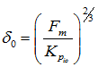
Now as the relationship between the applied radial force and the bearing elastic deformation has been established, the bearing stiffness could be calculated. The stiffness of rolling bearings is highly non-linear with the displacement of the inner ring with respect to the outer ring. On substituting F = Fm and ![]() into equations (3.5) and (3.10), we get
into equations (3.5) and (3.10), we get
| (3.24) |
and
| (3.25) |
Equating equations (3.24) and (3.25) gives the load deformation relationship for a single ball, which shares the maximum load (or which is in-line with the radial external load). The bearing stiffness k(xm) can be obtained by differentiating Fr with respect to displacement xm to give
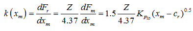 for ball-bearings for ball-bearings |
(3.26) |
and
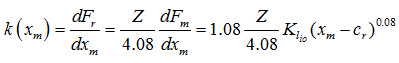 for roller bearings for roller bearings |
(3.27) |
The stiffness expressions are functions of xm, which varies with the steady load applied to the bearing. It should be noted that effectively we linearise the bearing stiffness at the static equilibrium. This is based on the assumption of small oscillations due to the small unbalance. If the dynamic forces are large (due to large unbalance), then large amplitudes of vibration are bound to occur at the bearing. In this case the bearing stiffness non-linearity play important role in machine response calculations. In subsequent sections the procedure for calculation of these stiffnesses are described.
The discussion above has made no reference to effects of movement of rolling elements around raceways on the bearing force-displacement relationship and the stiffness. In fact, although the number and location of rolling elements in the load zone changes as the bearing is rotated, the displacement and the stiffness of the bearing are little affected. Hence, the rotation of the bearing need not be allowed for stiffness calculations. For more detail in this regard readers are referred to Ragulskis et al., (1974). The stiffness characteristics of the rolling element bearing are studied under combined loading, i.e., under the action of the radial and axial forces, and the moment; hence there should be the corresponding radial, axial, and angular displacements. All the displacement are coupled, i.e., they depend upon the combined effect of all the forces and moments acting on the bearing. The stiffness matrix obtained is of the size 5´5. To obtain displacement a set of five equilibrium equations are solved for a given loading (Lim and Singh, 1990).