
Figure 13. ATPG and testing of a sequential circuit (Figure 10, Module 12, Lecture 1) with scan chain
In the last example we saw how scan chain can be used to set the flip-flops to desired value for testing. However, D-algorithm is required on the entire circuit (after removing flip-flops) to find the test pattern. Now we will see another advantage of scan chain, which eliminates the need for performing ATPG on the whole circuit. One needs to consider input of the nearest flip-flop from the fault site as an output line and perform ATPG on the sub-circuit lying in the cone of influence of the output line (i.e., input of the nearest flip-flop). This concept will be illustrated on a circuit example given in Figure 14.
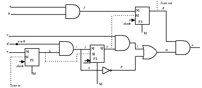
Figure 14. A sequential circuit with scan chain and s-a-0 fault at d
We will first illustrate the scheme of testing using scan chain where D-algorithm is applied on entire circuit and scan chain is used only to control the flip-flops; the procedure is shown in Figure 15. Figure 15 (a) illustrates D-algorithm applied on the full circuit of Figure 14 (after removing the flip-flops) where fault propagation path is taken as d-i-o-p-m-n. D-algorithm determines that h is to be 1 and g is to be 1; this implies that flip-flop F1 and F3 are to be set while F2 can be set or reset. Further, a =X, b =X, c =0 ,d =1, e =X would apply the pattern to sensitize and propagate the fault effect. So to make flip-flops F1 and F3 to be 1 and F2 to be X, pattern 1X1 is applied at Scan in input with three clock pulses keeping M=1; this is shown in Figure 15 (b). Finally, M is made 0 and test pattern a =X, b =X, c =0 ,d =1, e =X is applied, which propagates fault effect through primary output n; this is illustrated in Figure 15(c).