3. Scan Chain based Testing and ATPG for sequential circuits
In the last section we saw that shift register based testing of sequential circuits solved the problem of a large number of I/Os. However, the major drawback of the scheme is due to the huge area overhead; twice the number of flip-flops in the circuit under test is required in the shift register. The concept of Scan chin is motivated from the idea of shift register based testing, however, alleviates the problem of area overhead [1]. The basic idea in scan chain is to convert the flip-flops in the circuit under test itself to a shift register, rather than using a separate one. To elaborate, the circuit under test has two modes: (i) test (or scan chain) and (ii) working (or normal). In test mode the flip-flops are decoupled from the circuit and they are connected in form of a shift register (called scan chain). The input of the first flip-flop in the scan chain is taken out as a special input test pin called “Scan in” and the output of the last flip-flop in the scan chain is taken out as a special output test pin called “Scan out”. Now all the flip-flops are set as required by shifting bit values in the scan chain. Once the flip-flops are set they are removed from the scan chain and connected back to the circuit. So another advantage of scan chain based testing over shift register based testing is due to non requirement of set/reset lines. The basic concept of scan chain is shown in Figure 7.
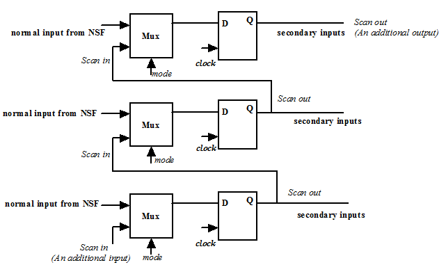
Figure 7. Scan chain in state flip-flop block
Figure 7 shows the state flip-flops with scan chain in a sequential circuit; other blocks are not shown for clarity. As discussed, flip-flops with scan-chain take inputs from two parts of the circuit (i) next state function block (when operating normally) and (ii) from the previous flip-flop in the chain (when in test mode); the first flip-flop in the scan chain takes input from a primary input “Scan in”. So in state flip-flop block with scan chain, all the flip-flops must have a 2X1 multiplexer. One input is from the next state function block and the other is from the previous flip-flop in the chain. The control input called mode basically decides the mode of operation; 1 for scan-chain and 0 for normal operation. Figure 7 shows this concept for a circuit with three flip-flops. Figure 8 shows a flip-flop used in scan chain called scan flip-flop and Figure 9 shows the block diagram representation of scan flip-flop. Figure 10 shows the flip-flops of Figure 7 in scan chain mode and Figure 11 shows the flip-flops of Figure 7 in normal mode. Figure 12 shows the basic block diagram of a sequential circuit with scan chain in both normal and test mode.