Figure 12.Sequentail circuit with scan chain: normal and test mode
4. ATPG and testing using scan chain in a sequential circuit: An Example
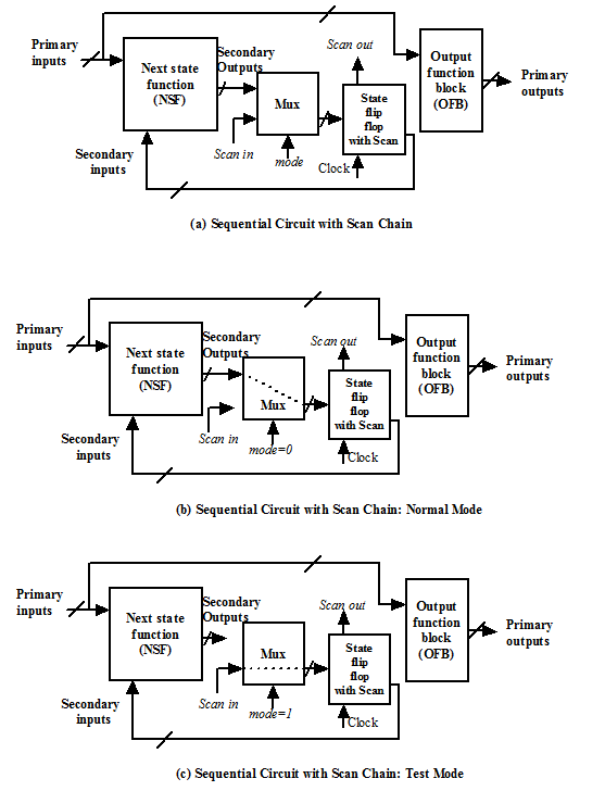
In this section we will discuss ATPG and testing of the sequential circuit discussed in last lecture (Module 12, Lecture 1, Figure 10), now with scan chain. The circuit with the flip-flops having scan chain compatibility is shown in Figure 13(a). As discussed about the circuit (in Module 12, Lecture 1, Figure 10), to test the s-a-0 fault at net j, the signal values at nets d and i are to be 1. So both the flip-flops are to be set to 1; this was achieved by making the set input as 1 and reset input as 0 in case of testing using set/reset flip-flops. In case of scan chain, to set the flip-flops, in the first step mode (M) is made 1. Making M=1, removes the next state function block from the circuit and the flip-flops are connected in a chain; this is shown by dotted lines in Figure 13(b). Two 1s are applied in the Scan in input at two clock pulses which makes d =1 and i =1. Now, the circuit is brought in normal mode by making M=0. In this stage testing is performed by making a =1, b =1, c =X which propagates the fault effect to the output; this is shown in Figure 13(c).