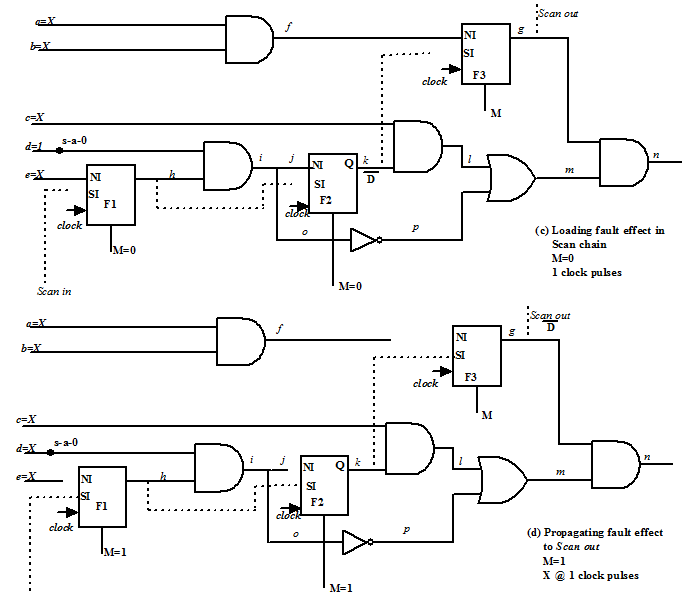
Figure 17-II. Fault effect propagation through scan chain (Step c and Step d for circuit of Figure 16)
Now the fault effect is to be brought out by the scan chain. This is achieved in two steps as shown in Figure 17-II. First, the effect D is loaded into the nearest flip-flop (F2) by applying a clock pulse keeping M=0; shown in Figure 17-II(a). Following that flip-flops are again brought into chain mode (by setting M=1) and 1 clock pulse is applied (with Scan in input as X), which brings the effect out through the Scan out output; shown in Figure 17-II(b).
5. ATPG and testing using partial scan chain in a sequential circuit: An Example
From the discussion in last lecture (Module 12, Lecture 1) we saw that a circuit with sequential dept
dseq needs dseqclock pulses and patterns to set the flip-flops (to required values) when testing is done using time frame expansion approach. In case of scan chain if there are nffflip-flops, then nff clock pulses are required to set/reset the flip-flops. As dseq≤ nff, test time is higher for scan chain based testing compared to time frame expansion method. Also, multiplexers are required in case of scan chains while no extra circuitry is required for time frame expansion method. Only ATPG complexity is lower in case of scan based testing. It may be noted that ATPG is off line exercise and test time is very expensive as patterns are applied by an automatic test equipment. However, scan based testing is still the most widely accepted technology. As discussed in the exercise of Lecture 1 Module 12, time frame expansion scheme cannot set/reset flip-flops which are cyclic (i.e., whose input is dependent on its own output). So scan based scheme or set/reset with shift register scheme is required for cyclic circuits.
A new scheme called “partial scan” came up taking ideas from both time frame expansion method and scan chain method [2]. The basic idea used in the scheme is to make scan enable only in those flip-flops which are cyclic and keep the remaining ones as normal. So we will have area overhead (because of MUX) only for those flip-flops which must be controlled directly and for the others, time frame expansion based indirect control can be used.
Circuit shown in Figure 18 will be used to illustrate the concept of partial scan.
Figure 18(a) shows a sequential circuit with D-algorithm applied after removing the flip-flops; the positions of the flip-flops are marked by double ended vertical arrows. It may be noted that two flip-flops are to be controlled to 1; net d is to be made 1 and net i is to be made 1. Making net d =1 is simple and can be achieved by applying c =1 and a clock pulse; this is shown in Figure 18(b). It may be noted that control of net d via F1 is by time frame expansion method; as dseq=1 for F1, so one clock pulse and one pattern is enough to control it. To make net i =1, we need b =1, d =1, m =1 (which makes f =1 via net e ) and a clock pulse. However there is a problem here. To make net m =1 we need j =1 which can be achieved by a =1, i =1. However to make i =1 we need m =1. This problem arises because flip-flop F2 is cyclic, as shown in Figure 18(b). So F2 cannot be controlled by time frame expansion method and it must have scan chain facility, as shown in Figure 18(c).