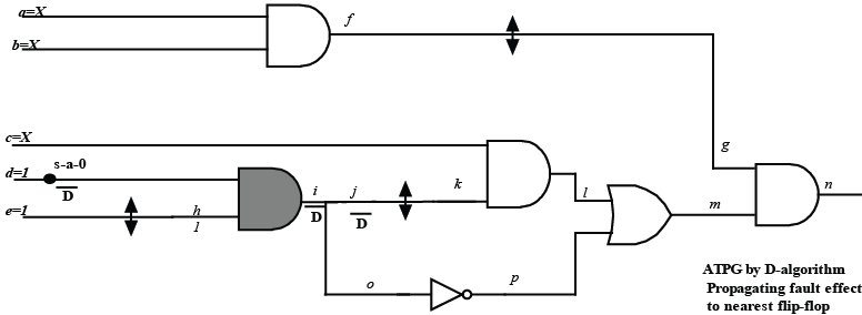
Figure 16. Fault sensitization and effect propagation to input of nearest flip-flop (of the circuit of Figure 14)
As already discussed, even in ATPG for sequential circuits, D-algorithm is performed on the full circuit with flip-flops removed. In the last example we saw the use of scan chain only to set/reset the flip-flops. Now we will see another use of scan chain in propagating the fault effect. So we need to just bring the fault effect to the input of the nearest flip-flop. This in turn requires ATPG on a sub-circuit whose output drives the input of the nearest flip-flop. In other words, ATPG is to be performed on the sub-circuit that lies in the cone of influence of the nearest flip-flop's input. Figure 16 illustrates that the nearest flip-flop from the fault site (s-a-0 at net d, of the circuit of Figure 14) is F2. So fault effect needs to be propagated to net j (which is input of F2). So, APTG is to be performed on the sub-circuit which lies in the cone of influence of net j, which includes inputs d,e and AND gate marked gray in Figure 16; test pattern is d =1, e =1 and fault effect D is propagated to net j . Obviously ATPG complexity is simplified. Now we will see how scan chain can propagate this fault effect out of the circuit.
The whole testing procedure, when fault is propagated through scan chain (for the circuit of Figure 16) is illustrated in Figure 17 I and Figure 17 II.
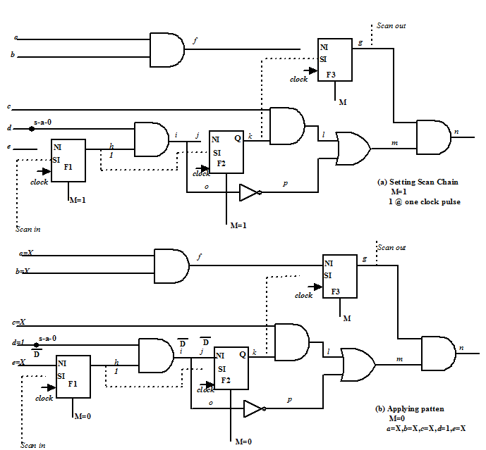
Figure 17-I. Fault effect propagation through scan chain (Step a and Step b for circuit of Figure 16)
In this case, as we are considering only a sub-circuit, so only F1 (i.e., net h ) needs to be made 1; this is shown in Figure 16. This is achieved by making M=1, giving 1 in Scan in input and a clock pulse; shown in Figure 17-I(a). After that M is made 0 and pattern d =1, e =X is applied to sensitize the fault and propagate the effect ( D) to net j via net i ; shown in Figure 17-I(b).