As discussed in the last lecture, three patterns were required to test the s-a-0 fault at net j:
(i) a =X, b =X, c =1 and clock pulse (ii) a =X, b =1, c =1 and clock pulse and (iii) a =1, b =1, c =X. Also it is to be noted that dseq=2, for the circuit.
Now, by using the set/reset flip-flops, we will see only two patterns are required to test the fault. By ATPG using D-algorithm, nets d and i are to be 1 for testing the fault. So both the flip-flops are set by the pattern: a =X, b =X, c =X, set (F1)=1, reset (F1)=0, set (F2)=1 and reset (F2)=0; this is shown in Figure 3(b). Finally, pattern a =1, b =1, c =X, set (F1)=0, reset (F1)=0, set (F2)=0 and reset (F2)=0 is applied to sensitize and propagate the effect of the fault to primary output; this is shown in Figure 3(c).
So, only two patterns can test the fault. However the most important point is “Irrespective of the value of dseq, only two patterns are required to test a sequential circuit with set/reset flip-flops”. The gain can be easily understood because any practical circuit has more than thousands of flip-flops. On the other hand, there is a big problem with the scheme that makes it impractical to be applied in a practical system. An input output block diagram of the circuit of Figure 3 is shown in Figure 4. It may be noted that it has 9 I/O pins (3 primary inputs + 1 primary output +2 x nffs set-reset lines, where nffs is the number of flip-flops and a clock). The largest number of I/O pins supported in most complicated packages is about 1024. So, for a circuit with thousands of flip-flops, this approach requires a package of thousands of I/O pins (for the 2 x nffs factor) with makes it impractical.
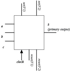
Figure 4. Input output block diagram of the circuit shown in Figure 3.
2.2.Set and reset by shift register
In the last sub-section we saw that flip-flops with set/reset capability can ease the testing and ATPG problem for sequential circuits. However, the main problem is the huge number of I/O lines that gets added to the chip. To avoid this issue of high I/Os, another technique called “set and reset by shift register” is used which uses a shift register and loads itself with the pattern required for setting the flip-flops. Now the set and reset lines of the flip-flops of the circuit (under test) are connected with the outputs of the flip-flops of the shift resister. The shift register has an input line and a separate clock (for shifting data) and an output line. So in this case only three extra I/O lines are required. ATPG and testing for the circuit shown in Figure 3, using shift register is illustrated in Figure 5.
As there are two flip-flops in the circuit under test, there are four flip-flops in the shift register. Now, set and reset lines of F1 (flip-flop) of the circuit under test are connected to output of SR1 and SR2 (flip-flops of register), respectively. Similarly, set and reset lines of F2 are connected to output of SR3 and SR4, respectively. As already discussed, testing the fault (s-a-0 at j ) requires the two flip-flops of the circuit to be set to 1. So the pattern is set (F1)=1, reset (F1)=0, set (F2)=1 and reset (F2)=0, which when mapped to the flip-flops of the shit register is SR1=1,SR2=0,SR3=1 and SR4=0. The pattern 1010 can be inserted in the shift register using four clock edges of S_clock . Once the shift register is loaded, the flip-flops F1 and F2 are set; this is shown in Figure 5(a). Now, another pattern 0000 is inserted in the shift register using four clock edges of S_clock; this makes the circuit under test ready to be operational. Following that input pattern a =1, b =1, c =X is applied to sensitize and propagate effect of the fault to primary output; this is shown in Figure 5(b). The block diagram of the circuit (under test) with shift register is shown in Figure 6. So in addition to original I/Os, three new I/Os get added namely, (i) S_clock , (ii) test in and (iii) test out .