1. Introduction
In the last lecture we have seen that the major problem in testing (and ATPG) of sequential circuits is difficulty in controlling secondary inputs (i.e., outputs of flip-flops) and difficulty in observing secondary outputs (i.e., inputs of flip-flops). In this lecture we will discuss various techniques to make the flip-flops controllable and observable, which convert a sequential circuit into virtual combinational one. Following that ATPG for combinational circuits would suffice for sequential circuits. However, for achieving this, additional circuitry, called design for test (DFT), will be put on-chip, which would add to extra area overhead.
In the next section we will explore different schemes to control and observe the flip-flops.
2. Controllability and observability of flip-flops
2.1 Set and reset lines
One of the simplest way to directly control flip-flops is through set-reset lines. Set-reset lines can directly make the output of a flip-flop to be 1/0 without any input and clock pulse. A D flip-flop with set-reset lines is shown in Figure 1 and its functionality is shown in Table 1.
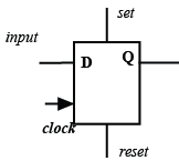
Figure 1. D-Flip-flop with set and reset
Table 1. Truth table for D flip-flop with set-reset lines
Input (D) |
Output (Q) |
set |
reset |
clock |
Don't care |
1 |
1 |
0 |
Don't care |
Don't care |
0 |
0 |
1 |
Don't care |
Don't care |
Illegal |
1 |
1 |
Don't care |
1 |
1 |
0 |
0 |
Clock edge |
0 |
0 |
0 |
0 |
Clock edge |
From the truth table it may be observed that set (reset) lines makes the output 1(0) irrespective of input D and clock pulse. However, both the set and reset lines cannot be made high simultaneously. Also, when the D-flip-flop functions normally, both set and reset lines are kept low.
Now we will see how use of this type of flip-flop helps in testing the circuit given in exercise of last lecture (Lecture 1, module 12). The circuit with a s-a-1 fault in the primary input line is shown in Figure 2 (a). Also, the flip-flop has set/reset lines. By D-algorithm, a test pattern would be: primary input =0, secondary input (other input of XOR gate)=0 and fault effect at primary output = D. So in Step-1 (Figure 2 (b)), set =1 and reset =0 (and and primary input =X); this makes output of flip-flop (i.e., secondary input) to be 1. In Step-2 (Figure 2 (c)), set =0, reset =0 and primary input =0; this sensitizes fault location as D and its effect propagates to the input of the flip-flop as D . Also a positive clock pulse is applied which transfers D to output of the flip-flop (primary output). These two steps complete ATPG (and testing) of the fault.
So it may be observed that the fault which was un-testable by time frame expansion method becomes testable using set/reset flip-flop. Further, one pattern is required to set/reset the flip-flops and another pattern (at primary inputs) is required to sensitize and propagate the fault effect to a primary output. So, unlike time frame expansion method where dseq+1 test patterns are required ( dseqpatterns to initialize the flip-flops and one pattern to sensitize/propagate fault effects), in case of set/reset flip-flops only two patters are required (one to set or reset the flops and one to sensitize/propagate fault effects). This saving in number of test patterns (i.e., test time) is illustrated in the circuit example of Figure 10 of the last lecture. The circuit (Figure 10 of Lecture 1, module 12) with set/reset flip flops is shown in Figure 3(a).