9.5.6 System equations of motion
In previous sections, we have obtained the elemental mass and stiffness matrices, and the internal and external force vectors. The objective of the present section is to demonstrate how to get system mass and stiffness matrices and force vectors in terms of the elemental mass and stiffness matrices and force vectors as given in equation (9.78). To illustrate the same let us take a two-element system with a rigid disc at node 2 as shown in Figure 9.11(a). Nodal displacement variables are shown in Fig. 9.11(b) at each of the three nodes. In Fig. 9.11(c) two elements are shown with corresponding internal shear forces and bending moments, where in symbols the superscript specifies the element number and the subscript specifies the node number. Here the disc is assumed to be at node 2 of element 1. T he elemental differential equations for elements 1 and 2, respectively, may be written as
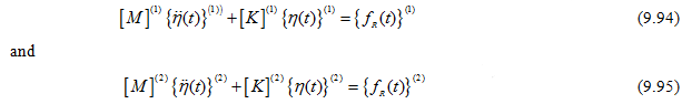
where superscript represent the element number. External forces are not considered.
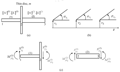
Figure 9.11 Two-element shaft with a rigid thin disc (a) discretisation of system, (b) nodal generalized coordinates, and (c) nodal forces and moments in elements.
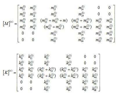
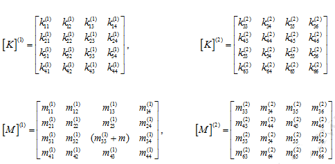
The mass and stiffness matrices for each of the element are obtained as in equation (9.78). By considering connectivity between various nodes the corresponding elemental mass and stiffness matrices are added to get the global mass and stiffness matrices. The elemental stiffness and mass matrices of equations (9.94) and (9.95), could be stated as follows (note that the poin t mass m is assumed to be attached to the element 1 at node 2)
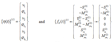
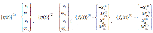
With the nodal displacement and internal force vectors are defined as
Relationship between the elemental (local) nodal displacements and the system (or global) displacements is established through the connectivity matrix given in Table 9.3.
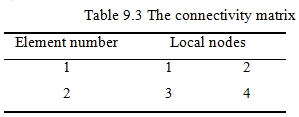
From Eq.(9.94) and connectivity matrix (Table 9.3), the system model as,
![]()
with