Concluding Remarks: The present chapter explains various simple rotor models in use to describe some of the important rotor behaviour, especially natural frequencies and critical speeds (i.e., the shaft spin at which the amplitude of rotor is maximum). Basic terminologies generally used to describe the rotor dynamic characteristics are introduced. For a single-DOF system the natural frequency and hence the critical speed decrease by small amount due to damping. However, in the Jeffcott rotor model it is shown that critical speed increases slightly due the increase in damping in the system. Apart from the amplitude of the rotor vibrations, it is shown that the phase between the force and the response is also important parameters to understand the rotor behaviour, especially at the critical speeds, where it changes of the order of 180°. The damping is shown to be an important factor in suppressing the rotor vibrations at the resonance. It is shown that the Jeffcott rotor is very a basic model to understand several important phenomena of the rotor system. However, several other phenomena also emanate from supports, and for this the basic understanding support dynamics is very important. The motivation of the next chapter would be to find out dynamic parameters of the rolling element and hydrodynamic bearings, and seals in isolation to the shaft. This will help in understanding some of the instabilities, which occurs due to support dynamics.
Exercise Problems
Exercise 2.1: For a single degree of freedom damped rotor system, obtain an expression for the frequency ratio ![]() for which damped response amplitude becomes maximum (i.e. location of the critical speed). Show that it is always more than the undamped natural frequency of the system. What is the maximum feasible value of damping ratio for under-damped system is possible.
for which damped response amplitude becomes maximum (i.e. location of the critical speed). Show that it is always more than the undamped natural frequency of the system. What is the maximum feasible value of damping ratio for under-damped system is possible.
[Hint: Differential the denominator of the unbalance response (Y/e) expression with respect to the frequency ratio and equate is to zero. Answer: ![]() ]
]
Exercise 2.2: Let us define a new frequency ratio in terms of the damped natural frequency, i.e., ![]() with
with ![]() . Obtain an expression for the amplitude ratio (Y/e) and the phase, Φ, in terms of the new frequency ratio defined. Plot the amplitude ratio and the phase versus the new frequency ratio and discuss the results. Obtain an expression for the frequency ratio (
. Obtain an expression for the amplitude ratio (Y/e) and the phase, Φ, in terms of the new frequency ratio defined. Plot the amplitude ratio and the phase versus the new frequency ratio and discuss the results. Obtain an expression for the frequency ratio (![]() ) for which damped response amplitude becomes maximum. What is the maximum feasible value of damping ratio for under-damped system is possible.
) for which damped response amplitude becomes maximum. What is the maximum feasible value of damping ratio for under-damped system is possible.
[Answer: 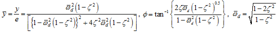 ; for
; for ![]() is a complex quantity. The maximum feasible value of damping ratio for under-damped system will remain the same
is a complex quantity. The maximum feasible value of damping ratio for under-damped system will remain the same ![]() ].
].
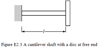
Exercise 2.3: Obtain transverse critical speeds of an overhung rotor system as shown in Figure E2.3. Take the mass of the disc, m = 10 kg, the diametral mass moment of inertia, Id = 0.02 kg-m2. The shaft diameter is 10 mm and total length of the span is 0.2 m. The shaft is assumed to be massless and its Young’s modulus E = 2.1 X 10¹¹ N/m2. Neglect the gyroscopic effect and take one plane motion only.
Influence coefficients are given as ![]()
[Answer: With the diametral mass moment of inertia effect two natural frequencies will exist: ![]() = 5.55 rad/s and
= 5.55 rad/s and ![]() = 144.12 rad/s. If the linear and angular motion is uncoupled then
= 144.12 rad/s. If the linear and angular motion is uncoupled then ![]() = 5.56 rad/s and
= 5.56 rad/s and ![]() = 71.80 rad/s. In case diametral mass moment of inertia is zero and no coupling between the linear and angular motion
= 71.80 rad/s. In case diametral mass moment of inertia is zero and no coupling between the linear and angular motion ![]() = 9.91 rad/s].
= 9.91 rad/s].
Exercise 2.4: Obtain the transverse critical speed of a rotor system as shown in Figure E2.4. Take the mass of the disc, m = 5 kg and the diametral mass moment of inertia, Id = 0.02 kg-m2. Take shaft length a = 0.3 m and b = 0.7 m. The diameter of the shaft is 10 mm. Neglect the gyroscopic effect.

For the present case, influence coefficients are given as ![]() , and
, and ![]() .
.
[Answer: ![]() = 12.14 rad/s and
= 12.14 rad/s and ![]() = 110.24 rad/s. With negligible diametral mass moment of inertia
= 110.24 rad/s. With negligible diametral mass moment of inertia ![]() = 5.98 rad/s]
= 5.98 rad/s]
Exercise 2.5: Obtain the bearing reaction forces and moments of an overhung rotor at rotor speeds of (i) 0.5 ![]() , (ii) 0.5(
, (ii) 0.5(![]() +
+ ![]() ) and (iii) 1.5
) and (iii) 1.5 ![]() ; where
; where ![]() and
and ![]() are the first and second bending natural frequencies, respectively. Take the mass of the disc, m = 10 kg, the diametral mass moment of inertia, Id = 0.02 kg-m2. The disc has a residual unbalance of 25 g-cm. The shaft diameter is 10 mm and the total length of the span is 0.5 m. The shaft is assumed to be massless and its Young’s modulus E = 2.1 X 10¹¹ N/m2. Take one plane motion only.
are the first and second bending natural frequencies, respectively. Take the mass of the disc, m = 10 kg, the diametral mass moment of inertia, Id = 0.02 kg-m2. The disc has a residual unbalance of 25 g-cm. The shaft diameter is 10 mm and the total length of the span is 0.5 m. The shaft is assumed to be massless and its Young’s modulus E = 2.1 X 10¹¹ N/m2. Take one plane motion only.
Influence coefficients are given as ![]() .
.
[Answer: ![]() = 15.60 rad/s and
= 15.60 rad/s and ![]() = 203.76 rad/s.; (i) RA = 1.4568 X 10⁹ N, MA = -1.1008 Nm (ii) RA= -3.2363 X 10¹² N, MA = 2.4240 X 10¹² Nm (iii) RA = -2.1125 X 10⁴ N, MA = 1.5831 X 10⁴ Nm].
= 203.76 rad/s.; (i) RA = 1.4568 X 10⁹ N, MA = -1.1008 Nm (ii) RA= -3.2363 X 10¹² N, MA = 2.4240 X 10¹² Nm (iii) RA = -2.1125 X 10⁴ N, MA = 1.5831 X 10⁴ Nm].
Exercise 2.6: Find transverse natural frequencies of an overhung rotor system as shown in Figure E2.6. Consider the shaft as massless and is made of steel with the Young’s modulus of 2.1(10)11 N/m2. A disc is mounted at the free end of the shaft with the mass of 10 kg and the diametral mass moment of inertia of 0.04 kg-m2. In the diagram all dimensions are in cm.
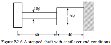
[Answer: For the pure translatory motion: 1200.7 rad/s and for pure rotary motion: 6561.9 rad/s. For analysis of combined translatoy motion refer Chapter 8]
Exercise 2.7: (a) While the Jeffcott rotor is whirling, with the help of the center of gravity, the center spinning of the disc and the bearing axis, draw their relative positions in an axial plane when the rotor is (i) below the critical speed (ii) at critical speed and (iii) above the critical speed. (b) Define following terms: natural frequency and critical speed of a rotor; synchronous and asynchronous whirls.
Exercise 2.8: In a design stage of a rotor-bearing system it has been found that its one of the critical speed is very close to the fixed operating speed of the rotor. List what are the design modifications a designer can do to overcome this problem.
Exercise 2.9: A cantilever shaft of 1 m length (l) and 30 mm diameter (d) has a 5 kg mass (m) attached at its free end, with negligibly small diametral mass moment of inertia. The shaft has a through hole parallel to the shaft axis of diameter 3 mm (di) , which is vertically below the shaft center, with the distance between the centers of the shaft and the hole as 6 mm (e). Consider no cross coupling in two orthogonal directions as well as between the linear and angular displacements; and obtain the transverse natural frequencies of the shaft system in two principal planes. Consider the shaft as massless and Young’s modulus E = 2.1 X 10¹¹ N/m2.
[Hint: Find the equivalent stiffness of the shaft in two principal directions and then obtain natural frequencies: ![]() and
and ![]() and
and ![]()
![]()
![]() = 70.55 rad/s,
= 70.55 rad/s, ![]() = 70.78 rad/s].
= 70.78 rad/s].