Equation (2.107) can be written as
(2.109) |
The solution of the above polynomial can be expressed as
![]()
or
(2.110) |
which gives critical speeds of the rotor system (the outer most negative sign has no meaning since frequency can not be negative). Hence, for the case when the rotor is not mounted at the mid-span, there are two critical speeds due to coupling of the linear and angular displacements. The above solution (i.e., equation (2.110)) can be more critically analysed as follows. It can be seen that terms inside the first square root is always positive, i.e., ![]() , since it can be rearranged as
, since it can be rearranged as
(2.111) |
It can be seen that the above condition be always true since all individual terms ωr, ωφ, ωrφ, and ωΦr are the real quantity. However, if the following condition is valid for terms inside the first square root
(2.112) |
then, it gives two real critical speeds ![]() since equation (2.104) gives two real roots. However, if the following condition prevails
since equation (2.104) gives two real roots. However, if the following condition prevails
(2.113) |
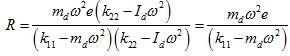
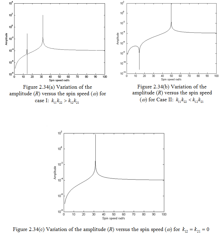
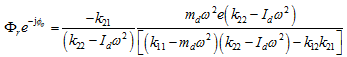
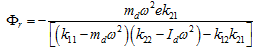
then, it gives only one real critical speed since the other root will be complex. Figures 2.34 (a) and (b) give these two cases, respectively. It can be seen that for the first case two distinct peaks corresponds to two critical speeds. For the second case only one critical speed is observed, and since system parameters chosen are different hence this value is different as compared to the previous case. However, there is anti-resonance with very low amplitude of vibrations. The following data is taken for the simulation: the disc mass = 1 kg, the unbalance mass eccentricity = 0.0001 m, the diametral mass moment of inertia = 0.03 kgm2, k11 = 1000 N/m, k22 = 6 N/m, k12 = 100 N/m and k21 = 0.5 N/m. For the disc at the center of the shaft span, we have k12 = k21 = 0, so Eqn.(2.114) becomes
 |
(2.114) |
which is same as discussed in the previous section for the Jeffcott rotor. The response is shown in Figure 2.34(c). It can be observed that it has only one critical speed, which may not coincide with the critical speeds obtained by equation (2.110) in Figures 2.34(a) and (b). However, there will be another critical speed corresponding to angular displacement and it is illustrated subsequently.
On substituting equation (2.106) into equation (2.101), we get
 |
(2.115) |
On equating imaginary parts of equation (2.115), we get
(2.116) |
which means there will not be any phase difference between the rotational displacement and the force also also since there is no damping in the system. On substituting phase information in equation (2.115), we get
 |
(2.117) |
which is the whirl amplitude of angular displacement and the condition of resonance can be obtained by equating the denominator of equation (2.117) to zero, which is same as in equations (2.106) and (2.110) for the linear displacement. For the disc at the center of the shaft span, we have k12 = k21 = 0, equation becomes
(2.118) |
which gives critical speeds as
 |
(2.119) |
which is the case when the disc is at the center of the shaft span, and the linear and angular displacements are uncoupled.
For the single plane motion from equation (2.91), we have
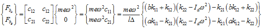
with
(2.120) |
The bearing force amplitude and phase can be obtained from equation (2.120). Bearing reaction forces will have similar trend in the variation with spin speed as that of the response, since it has the same denominator, Δ, as that of the response. It can be shown from equation (2.120) that forces transmitted through bearings have also a maximum at system critical speeds. These forces are dynamic forces and are superimposed on any steady loads, which may be present, for example due to gravity loading. In real systems which are designed to operate above their critical speeds, the machine would normally be run through the critical speed very quickly so that very large vibrations and forces associated with the resonance do not have sufficient time to build up. Same is true during the run-down where some form of braking may be employed. If the system is to run at the critical speed and vibrations are allowed to build up then either the shaft will fracture and a catastrophic failure will result, or there may be sufficient damping in the system to simply limit the vibration and force amplitudes to some very large (however, tolerable) value.