14.9.7 Cross-correlation Function
It is sometimes necessary to determine the spectral density or autocorrelation function of a quantity which is a combination of a number of different randomly varying quantity, for each of which the spectral density or autocorrelation is already known. We may be interested in for example in the relative motion of two points or the motion of the same point in two orthogonal directions as in rotors. It is therefore necessary that we be able to determine the spectral density and autocorrelation function of a sum in terms of those of its components.
Consider a randomly varying quantity s(t) made up of two quantities x(t) and y(t) so that s(t) = x(t) + y(t). The autocorrelation function of the combined signal Rs(f) can be expressed as
|
(14.66) |
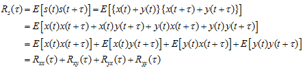
where ![]() are autocorrelation functions, and
are autocorrelation functions, and ![]() are cross-autocorrelation functions. Cross-correlations are zero if two signals x(t) and y(t) are uncorrelated (for the case of rotor displacements in two orthogonal directions since these displacements are due to a common unbalance force so they will be correlated, however, two mode shapes of a single system will be uncorrelated since mode shapes are independent displacement vectors). For the stationary process, we have
are cross-autocorrelation functions. Cross-correlations are zero if two signals x(t) and y(t) are uncorrelated (for the case of rotor displacements in two orthogonal directions since these displacements are due to a common unbalance force so they will be correlated, however, two mode shapes of a single system will be uncorrelated since mode shapes are independent displacement vectors). For the stationary process, we have
|
(14.67) |
14.9.8 Coherence Function
The coherence function (or coherency squared function) is defined as
|
(14.68) |
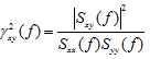
Where sxy is the spectral density.
and stratifies for all f, with
|
(14.69) |
14.10 Protection against spurious signals
When studying vibration signals it is important to be sure that the signal under consideration represents vibration, which is actually present. In some situations it is possible for the electrical signal received by the measuring system to indicate the presence of vibration that does not in fact exist. Alternatively, a spurious signal may be superimposed on a genuine vibration signal and thereby upset its measurement. The two most common causes of the spurious signals are ‘noise’ and ‘runout’.
14.10.1 Electrical noise
The electrical noise may arise from a number of different sources: (i) random electron motion (ii) local magnetic fields arcing and (iii) earth loop faults.
Noise created by the random motion of electrons is known as ‘thermal’ noise. It is generally only of the order of μV, however, and is not normally significant in measurements of rotating machinery vibrations. The noise set up by local magnetic fields is usually of the order of mV and is more significant. It is set up as a consequence of magnetic fields in nearby electrical apparatus introducing noise signals in electrical leads conveying the signal that is to be measured. Some protection against this type of noise-generating mechanism can be obtained by screening the leads with a high-conductivity material, which is earthed. A similar effect can also arise when one piece of instrumentation is sited close to another, because the magnetic fields inside one can induce signals in the circuit of the other. In this instant the entire instrument should be screened by placing it inside a metal case. Another source of electromagnetic radiation which can induce noise signals is that emitted as a consequence of electrical arcing in switches and commutators. This type of noise-generating mechanism can also be protected against by screening as described above. The earth-loop noise can occur when there are too many earth connections in the instrumentation.
14.10.2 Run-out
Proximity transducers used to monitor rotating machinery vibrations depend for their operation on a change in transducer reactance. Changes in transducer reactance may be present as a consequence of either mechanical or electrical run-out. The mechanical run-out is present when the shaft section being monitored by the transducer is eccentric to the axis of rotation, or has significant surface undulations, alternatively, the shaft may be bent. Each of these conditions results in motion of the shaft surface towards or away from the transducer tip when the shaft is rotated, the motion which is not caused by shaft vibration. To remove mechanical run-out the shaft must be re-machined; if the shaft is bent it must be straightness prior to re-machining. The electrical run-out is present when, around the shaft circumference, there are variations in the permeability of the shaft material to the electrical field set up by the transducer. This might be caused by residual magnetic fields in the shaft surface (due for example to particular methods of manufacture or non-destructive testing), by material in-homogeneity or by local residual stresses. Residual magnetic fields can be removed by degaussing, if residual magnetism is not the cause of the electrical run-out then special treatments such as burnishing, micropeening, or electroplating may be necessary. The amount of mechanical run-out present can be determined by mounting a dial test indicator next to the transducer, and noting the variation in reading when the shaft is rotated slowly. The electrical run-out present may be determined by noting the transducer reading when the shaft is rotated at low speed (sufficient to obtain a reading on the measuring instrument but not so high as to cause the shaft to vibrate). The subtraction of the mechanical run-out vector from the measured vector then gives the electrical run-out vector. All run-out vectors should be removed from signal measurements to enable true vibration vectors to be recorded. Such ‘nulling’ is carried out by subtracting the total residual run-out vector from the measured vector, as indicated in Figure 14.43.
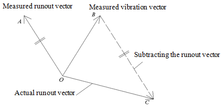
Figure 14.43 Nullifying of run-outs from measured signal