which gives Ke = 9021.2 Nm/rad. The flexible natural frequency of the equivalent two-disc rotor system as shown in Figure 6.34 is given as
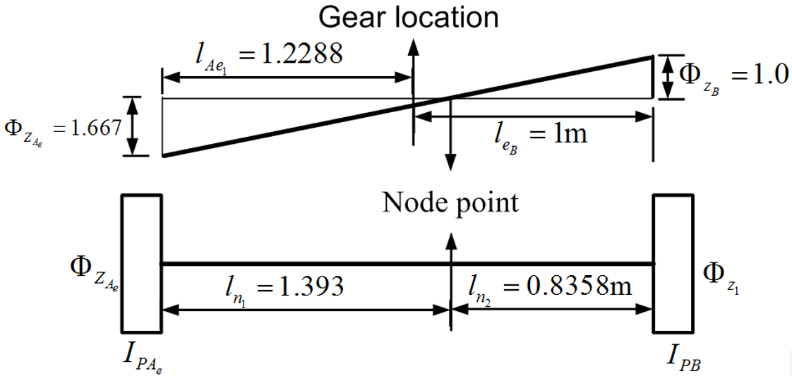
Figure 6.35 Mode shape and nodal point location in the equivalent system
The node location can be obtained from Figure 6.35 as
which can be written by noting equation (6.13), as
The negative sign indicates that both discs are at either end of the node location. The absolute location of the node position is given as
Also from Figure 6.35, we have
which gives
Hence, the node is on shaft B at 0.8356 m from disc B. Alternatively, from similar triangle of the mode shape (Figure 6.35), we have