6.6 Simple Geared Systems
In actual practice, it is rare that the rotor system has a single shaft (with either uniform or stepped cross sections) with multiple discs as we analysed in previous sections. In some machine the shaft may not be continuous from one end of the machine to the other, but may have a gearbox installed at one or more locations, for example, in stone crusher unit between motor and crusher, in automobile between engine and wheels (or propeller shaft), in rolling mills between main motor and main shaft and then between various stages of shafts, etc. Hence, shafts will have different angular velocities as shown in Figure 6.30(a). For the purpose of analysis the geared system must be reduced to system with a continuous shaft so that they may be analysed for torsional vibrations by methods as described in preceding sections (i.e., two-disc or three-disc or multi-disc rotor system).
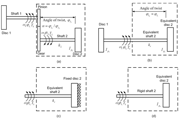
Fig. 6.30 (a) Actual geared system (b) An equivalent system without geared system (c) The equivalent system with disc 2 as fixed and (d) The equivalent system with shaft 2 as rigid