6.7 TMM for Branched Gear Systems
For rolling mills, textile machineries, the marine vessel power transmission shafts, and machine tool drives; there may be many rotor inertias in the system and gear box may be a branch point where more than two shafts are attached. In such cases where there are more than two shafts attached as shown in Fig. 6.40 to the gearbox, the system is said to be branched. It has three braches A, B and C; and each branch has multiple discs, e.g. (p + 1), (q + 1), and (r + 1) number of discs (including gears) in branches A, B and C, respectively. Such system can not be converted to a single shaft system as we could do to the two-shaft geared system as discussed in previous section. Since now the system contain several discs hence, it is a multi-DOF system and hence the analysis of the branched system would now be done by more general procedure, i.e. the TMM.
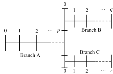
Fig. 6.40 A branched multi-DOF rotor system
For the branched system as shown in Figure 6.40, state vectors for different branches can be written as
| (6.84) |
where [A], [B], and [C] are overall transfer matrices for branches A, B, and C; respectively.
Branch A: For branch A, taking ![]() as the reference value for the angular displacement and since the left hand end of branch A is free end, hence for free vibrations we have
as the reference value for the angular displacement and since the left hand end of branch A is free end, hence for free vibrations we have![]() . Equation for branch A takes the following form
. Equation for branch A takes the following form
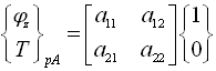 |
(6.85) |
which can be expanded as
| (6.86) |
Branch B: At branch point, between shafts A and B, we have
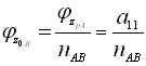 |
(6.87) |
where nAB is the gear ratio between shafts A and B. For branch B, ![]() since the right hand end of the branch is free. For branch B from equation (6.840, and noting condition described by equation (6.87), we have
since the right hand end of the branch is free. For branch B from equation (6.840, and noting condition described by equation (6.87), we have
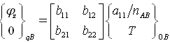 |
(6.88) |