where Tr and Te is the kinetic energies in the real and equivalent system, respectively; ![]() and are angular frequencies of disc 2 of the real
and are angular frequencies of disc 2 of the real ![]() and equivalent (
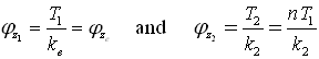
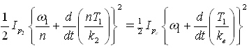
and equivalent (![]() )systems, respectively. These angular velocities contain nominal angular speed, w, and torsional frequencies, φz , as given in eqn.(6.79) . Equations(6.79) can be equated and is written as
)systems, respectively. These angular velocities contain nominal angular speed, w, and torsional frequencies, φz , as given in eqn.(6.79) . Equations(6.79) can be equated and is written as
| (6.80) |
where![]() are the angular velocities due to torsion of shaft 2 in the actual and equivalent systems, respectively. It can be seen from Figure 6.30(d) that
are the angular velocities due to torsion of shaft 2 in the actual and equivalent systems, respectively. It can be seen from Figure 6.30(d) that ![]() andω1 and ω2 are angular frequencies of the shaft 1 and 2, respectively. We have the following basic relations
andω1 and ω2 are angular frequencies of the shaft 1 and 2, respectively. We have the following basic relations
 |
(6.81) |
where T1 and T2 are torques at gears 1 and gear 2, respectively, in actual system. Noting equation (6.81), equation (6.80) can be written as
 |
(6.82) |
On substituting equation (6.78) in equation (6.82), we get

which simplifies to
 |
(6.83) |
where ![]() are, respectively, the equivalent shaft stiffness and the equivalent polar mass moment of inertia of the geared system referred to the ‘reference shaft’ speed, i.e. shaft 1. The general rule, for forming the equivalent system for the purpose of analysis, is to divide all shaft stiffness and rotor polar mass moment of inertia of the gear system by n2 (where n is the gear ratio). It could be seen that a gear system is reduced to two-disc rotor system (Fig. 6.31) for which we have already discussed the torsional free vibration analysis previously. When analysis is completed, it should be remembered that the elastic line of the mode shape of the equivalent system (i.e., the line abc in Fig 6.31) is modified for the real system by dividing the displacement amplitudes of the equivalent shaft by the gear ratio n as shown in Figure 6.31 by the line abde. It should be noted that angular displacements shown in Fig. 6.31 are now that of discs 1and 2.
are, respectively, the equivalent shaft stiffness and the equivalent polar mass moment of inertia of the geared system referred to the ‘reference shaft’ speed, i.e. shaft 1. The general rule, for forming the equivalent system for the purpose of analysis, is to divide all shaft stiffness and rotor polar mass moment of inertia of the gear system by n2 (where n is the gear ratio). It could be seen that a gear system is reduced to two-disc rotor system (Fig. 6.31) for which we have already discussed the torsional free vibration analysis previously. When analysis is completed, it should be remembered that the elastic line of the mode shape of the equivalent system (i.e., the line abc in Fig 6.31) is modified for the real system by dividing the displacement amplitudes of the equivalent shaft by the gear ratio n as shown in Figure 6.31 by the line abde. It should be noted that angular displacements shown in Fig. 6.31 are now that of discs 1and 2.
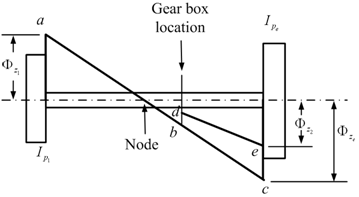
Figure 6.31 The elastic line in the equivalent and original systems