It is assumed that gears and shafts have negligible polar mass moment of inertia as compared to discs in the geared rotor system (This assumption could be relaxed with the increase of one more disc in the equivalent rotor system, for example for Fig. 6.30(a) from two-disc rotor system to three-disc rotor system). In the actual system as shown in Figure 6.30(a), k2 is the torsional stiffness of the shaft between gear 2 and disc 2, and ![]() is the polar mass moment of inertia of disc 2. Let the equivalent system as shown in Fig. 6.30(b) has the shaft torsional stiffness ke and the disc polar mass moment of inertia Ipe The strain and kinetic energy values must be the same in both the real and dynamically equivalent systems for the equivalent theoretical model to be valid.
is the polar mass moment of inertia of disc 2. Let the equivalent system as shown in Fig. 6.30(b) has the shaft torsional stiffness ke and the disc polar mass moment of inertia Ipe The strain and kinetic energy values must be the same in both the real and dynamically equivalent systems for the equivalent theoretical model to be valid.
Equivalent stiffness: Let the disc with the polar mass moment of inertia,![]() , is imagined to be held rigidly in both the real (Fig. 6.30a) and equivalent (Fig. 6.30c) systems, while the pinion shaft 1 is rotated through an angle of
, is imagined to be held rigidly in both the real (Fig. 6.30a) and equivalent (Fig. 6.30c) systems, while the pinion shaft 1 is rotated through an angle of ![]() at the input to gearbox (i.e., at the pinion). Shaft 2 is rotated through an angle
at the input to gearbox (i.e., at the pinion). Shaft 2 is rotated through an angle ![]() at the gear 2, where n is the gear ratio. It is the ratio of the angular speed of the driving gear (pinion) to that of the driven gear, i.e.
at the gear 2, where n is the gear ratio. It is the ratio of the angular speed of the driving gear (pinion) to that of the driven gear, i.e.
![]()
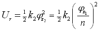
where ω is the spin speed of the gear and N is the number of teeth of the gear. That means to get the speed of output shaft (or gear) we need to divide the speed of input shaft (or pinion) by the gear ratio. The speed ratio, train value, and kinematic coefficient are other terms used for gear ratio; however, these are an inverse of the gear ratio, i.e. the ratio of the angular speed of the driven gear to that of the driving gear. In the present text consistently we would be using the gear ratio only. The sense of rotation of gear can be taken care by two ways, either observing the sense of rotation in the diagram of the gear train itself or by attaching positive/negative sign to indicate the same/opposite sense of rotation, and we would follow the convention of the former one. Hence, the strain energy stored in shaft 2 of the actual system, for a twist of ![]() at the input to the gear box, can be written as
at the input to the gear box, can be written as
 |
(6.76) |
where Ur is the strain energy in the real system. While applying the same angular displacement at the input of the gear box to the equivalent rotor system (Fig. 6.30c) results in the stain energy stored in the equivalent shaft, and can be expressed as
| (6.77) |
where Ue is the strain energy in the equivalent system, and since we have ![]() . On equating equations (6.76) and (6.77), it gives the equivalent stiffness as
. On equating equations (6.76) and (6.77), it gives the equivalent stiffness as
| (6.78) |
Equivalent polar mass moment of inertia: Now we consider the shaft 2 as a rigid shaft in both the real and equivalent systems (Fig. 6.30d), so that angular motion of gear 2 and disc 2 is same. That means whatever motion at pinion is given to: (i) for the real system the disc 2 gets same motion as the gear 2, (ii) for the equivalent system the disc 2 gets same motion as the pinion itself. Kinetic energies of both the real and equivalent rotor systems must also be equated
| (6.79) |
with
![]()