Eigen values and eigen vectors are given as (by the MATLAB of the above matrix)
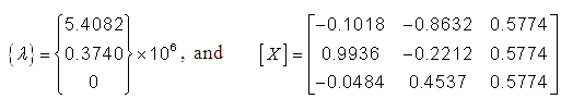
where the columns of matrix [X] represent the mode shapes corresponding to eigen values given in rows of the vector {λ}. Hence, natural frequencies are obtained as
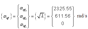
These are exactly the same as obtained earlier. The mode shape can be normalised as (in each column elements is divided by the corresponding first row element, e.g. 0.9936/(-0.018) = -9.76), -0.0484/(-0.018) = 0.48, -0.2212/(-0.8632) = 0.26, etc.)
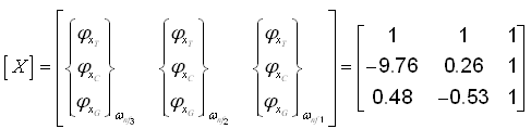
These mode shapes are exactly same as in Fig. 6.15.
6.4.2 An indirect approach
From the previous method, it is clear that for a particular natural frequency a unique mode shape exists. In the present method, the information regarding the possible mode shapes would be utilised to get the corresponding natural frequencies. In the case when the shaft has steps, then the first step would be to reduce the actual shaft to an equivalent shaft of a uniform diameter as shown in Figure 6.16(a). are the length of shaft segments between discs 1 and 2, and between discs 2 and 3, respectively; and Ipi is the polar mass moment of inertia of a disc (with i = 1, 2, 3).
For the three-disc rotor system, three natural frequencies are expected and correspondingly three natural (or normal) modes of vibrations are possible. Since for free-free boundary conditions one of the modes (corresponding to the torsional natural frequency of the value equal to zero) would be the rigid-body mode, in which all the discs have same motion. Apart from the rigid body mode, there will be two possible flexible natural modes of vibration, in which all discs reach their extreme positions at the same instant of time and all pass through their equilibrium position at the same instant of time. There will be a distinct torsional natural frequency for each of these two normal modes.
In the first flexible mode (corresponding to the first non-zero natural frequency) there will be a single node (a point where there will not be any angular displacement) either between discs 1 and 2 or between discs 2 and 3 (see Figure 6.16(b)). It depends upon the relative polar mass moment of inertia of discs, and the stiffness of shaft segments. However, the oscillations of the outside discs 1 and 3 will be in the anti-phase because of the single-node of vibration mode. The disc 2 will have same or opposite phase with disc 1 (or disc 3) and it depends upon the node position. It is assumed in Figure 6.16(b) that the node lies between discs 2 and 3.
While in the second flexible mode there are two nodes, one between discs 1 and 2 and the other between discs 2 and 3 (as shown in Fig. 6.16(c)). Oscillations of outside discs (1 and 3) are now in-phase, while the inside disc will have opposite phase with respect to both discs 1 & 3.
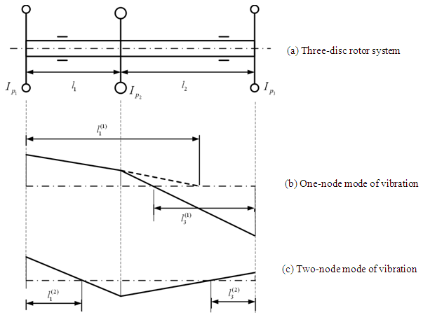
Fig. 6.16 A three-disc rotor system with two possible flexible modes of vibration
One-node mode of torsional vibration
Two-node mode of torsional vibration