Node locations in the second and third modes can be obtained as follows:
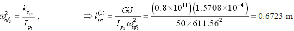
Second mode: Only single node (Fig. 6.15b) is present between the coupling and the generator. Hence, from the node position to the generator a single-DOF rotor system can be assumed with the length of shaft as![]() (superscript corresponding to single-node mode and subscript gn represent from the generator to the node location) and polar mass moment of inertia as Ip3 , this gives
(superscript corresponding to single-node mode and subscript gn represent from the generator to the node location) and polar mass moment of inertia as Ip3 , this gives
Third mode: Two nodes are present (Fig. 6.15c), thus two single-DOF rotor systems (i) from the first node to turbine, and (ii) from the second node to the generator can be considered. Hence the node locations are obtained as
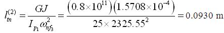
and
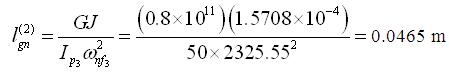
where the superscript in the length represent two-node mode and subscript tn represents from turbine to nearest node.
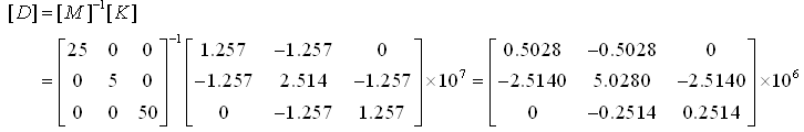
Now using the eigen value problem procedure, the above problem will be solved again. This will demonstrate how powerful this procedure is especially for multi-DOF systems. The mass and stiffness matrices can be given as
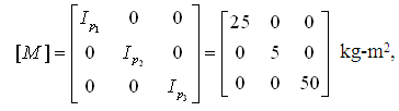
and,
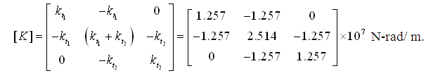
Hence, for the eigen value problem the matrix becomes