On multiplying both sides by the inverse of mass matrix in equation (6.33), we get a standard eigen value problem of the following form
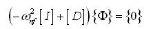 |
(6.34) |
with
![]()
where [I] is the identity matrix. The eigen value and eigen vector of the matrix [D] can be obtained conveniently by hand calculations for the matrix size up to 3×3, however, for the larger size matrix from multi-DOF rotor systems any standard software (e.g., MATLAB, SCILAB, etc.) could be used. The square root of eigen values will give the natural frequencies and corresponding eigen vectors as mode shapes (i.e., relative amplitudes). These methods would now be illustrated through a numerical example.
Example 6.4 Obtain torsional natural frequencies of a turbine-coupling-generator rotor system as shown in Figure 6.14. The rotor is assumed to be supported on frictionless bearings and shafts are connected by the rigid coupling. The polar mass moment of inertia of the turbine, coupling and generator are Ip1= 25 kg-m2, Ip2 = 5 kg-m2 and Ip3 = 50 kg-m2, respectively; and these are assumed to be thin discs. Take the modulus of rigidity of the shaft as G = 0.8 X 10¹¹ N/m2. Assume the shaft diameter as uniform throughout and is equal to 0.2 m and the length of shafts between the bearing-turbine-coupling-generator-bearing are 1 m each so that the total span is 4 m. Consider the shaft as massless.
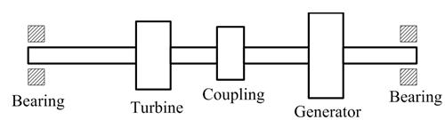
Figure 6.14 A turbine-coupling-generator set
Solution: It should be noted that for free-free end conditions both ends of the shaft segments (i.e., between bearing and turbine, and generator and bearing) will not have torsional displacements. Hence, only shaft segments between the turbine and the coupling (let us take it as shaft 1), and between the coupling and the generator (shaft 2) will have the torsional stiffness effect. Hence, we have the following data
