and
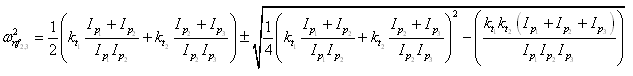
Natural frequencies of three-disc rotor system are given as (equation(6.35) )
ωnf1=0
and
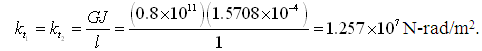
On substituting values of various parameters of the present problem in above equation, it gives
![]()
The mode shape (relative angular displacements of various discs) can be obtained as summarised in Table 6.1 (refer equations (6.36) and (6.37)). Fig. 6.15 shows mode shapes with node locations, in drawing T, C and G represent location of the turbine, coupling and generator, respectively.
Table 6.1 Relative angular displacements of various discs
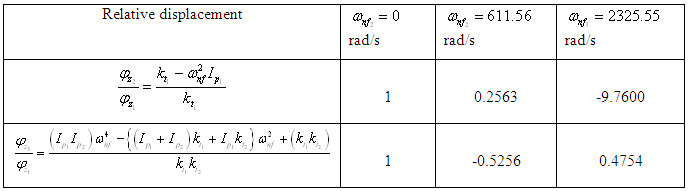
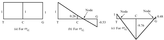
Fig. 6.15 Three mode shapes corresponding to three torsional natural frequencies