6.2 A Two-Disc Torsional Rotor System
A two-disc torsional system is shown in Figure 6.4. In this case the whole of the rotor is free to rotate about the centre line of the shaft, as the shaft is mounted on frictionless bearings. Hence, it has free-free end condition, and the application of which can be found in an aircraft when it is flying and whole structure has torsional vibrations due to aerodynamic forces.
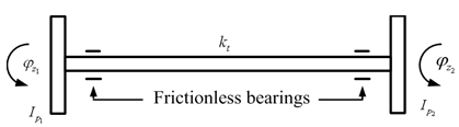
Figure 6.4 A two-disc torsional system
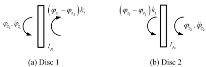
Let ![]() are angular displacements of thin discs 1 and 2, respectively. For both angular displacements the counter clockwise direction is chosen as positive direction.
are angular displacements of thin discs 1 and 2, respectively. For both angular displacements the counter clockwise direction is chosen as positive direction. ![]() are polar mass moment of inertia of discs 1 and 2, respectively. From the free body diagram of discs as shown in Figure 6.5, we have
are polar mass moment of inertia of discs 1 and 2, respectively. From the free body diagram of discs as shown in Figure 6.5, we have
![]()
and
![]()
where kt is the torsional stiffness of the shaft, and let ![]() be the relative twist of the shaft ends. Above expressions give the following equations of motion
be the relative twist of the shaft ends. Above expressions give the following equations of motion
| (6.6) |
For free vibrations, we have SHM ![]() where
where ![]() is the amplitude and ωnf is the natural frequency), so the solution will take the form
is the amplitude and ωnf is the natural frequency), so the solution will take the form
| (6.7) |
Substituting equation (6.7) into equation (6.6), it gives
| (6.8) |
Noting equation (6.3), equation (6.8) can be assembled in a matrix form in frequency domain as
| (6.9) |
with
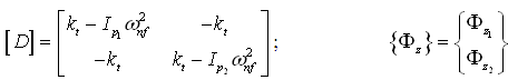
The non-trial solution of equation (6.9) is obtained by taking determinant of the matrix [D] equal to zero, as
![]()