where ![]() are node position in real system (Fig.6.9(a)). Equation (6.24) can be combined as
are node position in real system (Fig.6.9(a)). Equation (6.24) can be combined as
| (6.25) |
So once ![]() is obtained from equation (6.22), the location of the node in the actual shaft can be obtained from equation (6.25). The final location of the node on the shaft in the real system is given in the same proportion as in the shaft of equivalent system in which the node occurs.
is obtained from equation (6.22), the location of the node in the actual shaft can be obtained from equation (6.25). The final location of the node on the shaft in the real system is given in the same proportion as in the shaft of equivalent system in which the node occurs.
Example 6.3 Consider a stepped shaft with two discs as shown in Fig. 6.10. The following shaft dimensions are to be taken:
![]() Take the modulus of rigidity of the shaft as
Take the modulus of rigidity of the shaft as ![]() . Discs have polar mass moment of inertia as
. Discs have polar mass moment of inertia as ![]() . Obtain torsional natural frequencies, mode shapes, and the location of the node. Neglect the inertia of the shaft.
. Obtain torsional natural frequencies, mode shapes, and the location of the node. Neglect the inertia of the shaft.
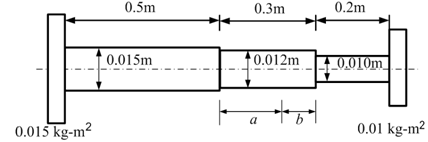
Fig. 6.10 A stepped shaft with two discs
Solution: Let us represent shaft segments towards the left, middle and right sides as 1, 2 and 3, respectively. For the present problem the shaft has following data
![]()

For the stepped shaft the first step would be to obtain the equivalent length with respect to the reference shaft 3 that has diameter of 0.01 m, as
![]()