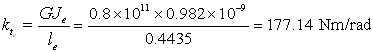
Hence ![]() , Now, the equivalent stiffness can be calculated as
, Now, the equivalent stiffness can be calculated as
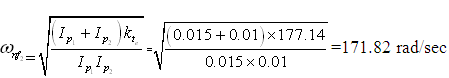
The torsional natural frequency of the rotor system can be calculated as
Relative displacements of the rotor system would be
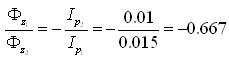
which means disc 1 would have 0.0667 times the angular displacement amplitude as compared to the disc 2, however, in the opposite direction. It is interesting that relative displacement remains the same irrespective of shaft characteristics (i.e., stepped, uniform, etc.) and its stiffness. However, the node position depends upon the shaft characteristics and its stiffness, and can be obtained as for the equivalent shaft as
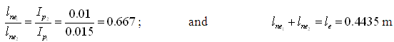
Hence, we get the node location as ![]() (i.e., 0.266 m from disc 2 in the equivalent system see Fig. 6.11). Hence, we have
(i.e., 0.266 m from disc 2 in the equivalent system see Fig. 6.11). Hence, we have ![]() . This means the node will be in second (middle) shaft segment. The location in actual rotor system would be
. This means the node will be in second (middle) shaft segment. The location in actual rotor system would be
with
![]()
and
![]()
Hence, we have the position of the node in actual system, from above equations, as:
![]()
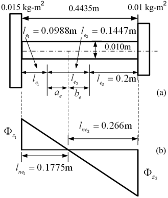
Fig. 6.11 (a) Equivalent system and (b) its mode shape and node position
Answer