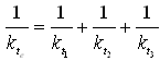
Since torsional stiffness corresponding to different shaft segments are connected in series, the equivalent torsional stiffness can be written as
 |
(6.20) |
where kt is the torsional stiffness, subscripts: 1, 2, 3 represent the shaft segment number and the subscript e represents the equivalent. Nothing equation (6.1), equation (6.20) becomes
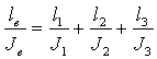 |
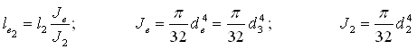
where ![]() represents the length of the shaft segment and J is the polar moment inertia of the shaft cross-sectional area. Above equation can be written as
represents the length of the shaft segment and J is the polar moment inertia of the shaft cross-sectional area. Above equation can be written as
| (6.21) |
with
![]()
where ![]() are equivalent lengths of shaft segments having the equivalent shaft diameter d3, and
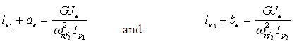
are equivalent lengths of shaft segments having the equivalent shaft diameter d3, and ![]() is the total equivalent length of the unstepped equivalent shaft as shown in Figure 6.9(b). Let us assume that the node position in the equivalent shaft system comes out in the second shaft segment from the previous section analysis of the two-disc uniform-shaft rotor system with free-free boundary conditions (in case the node position comes in the first shaft segment or in the third shaft segment then also the analysis would the remain the same and parameter values and its sign would take care of the actual position of the node). Noting equations (6.15) and (6.16), the node location in the equivalent shaft from Figure 6.9(b) can be obtained as
is the total equivalent length of the unstepped equivalent shaft as shown in Figure 6.9(b). Let us assume that the node position in the equivalent shaft system comes out in the second shaft segment from the previous section analysis of the two-disc uniform-shaft rotor system with free-free boundary conditions (in case the node position comes in the first shaft segment or in the third shaft segment then also the analysis would the remain the same and parameter values and its sign would take care of the actual position of the node). Noting equations (6.15) and (6.16), the node location in the equivalent shaft from Figure 6.9(b) can be obtained as
 |
(6.22) |
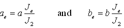
with
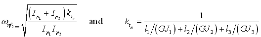
From equation (6.22), the node position (i.e., ae or be in Fig. 6.9(b)) can be obtained, the corresponding node location in the real shaft system can be obtained as explained below. From equation (6.21), we have
 |
(6.23) |
Since equation (6.23) is for the shaft segment in which node is assumed to be present, we can write
 |
(6.24) |