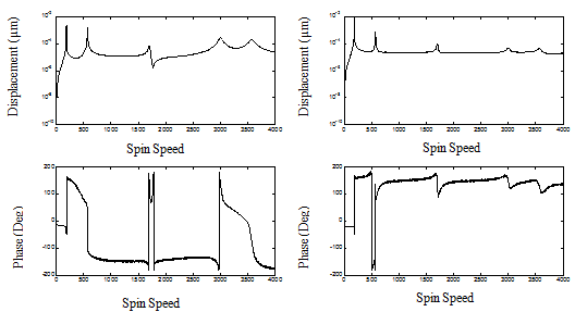
Fig. 13.43 Variation of the unbalance response amplitude and phase with the spin speed (residual unbalances, with damping and 5% noise) (left) for the left measuring plane (right) for the right measuring plane
Next, with the help of responses due to unknown residual unbalances (i.e., the concentrated at discs and distributed over the shaft in the spiral form) and with responses by adding known trial masses, it has been attempted to get unbalance information on the two balancing plane which would balance the rotor up to second critical speed. Trial unbalances are given in the form of small amount of mass added at a particular phase angle (4 gm at 40º) with respect to a reference position on the disc, assuming that all trial masses are added at a fixed radial distance from the centre of the balancing plane. Table 13.6 gives the calculated unbalances which approximate the distributed unbalance over the entire shaft. Fig. 13.44 shows the superposed plots of responses plotted before balancing and after balancing. Here neither damping nor noise is considered. The plot reveals that the rotor is balanced up to second critical speeds and the phase also changes accordingly. Figs. 13.45 to 13.47 give the plot of responses in different conditions involving the damping and the noise. Figs. 13.44 and 13.47 show the case of balancing with three and five percent noises, respectively. So from the graphs it is evident that even with five percent noise, it is possible to balance the flexible rotor. Moreover as here we considered only two plane balancing so only first two modes are getting balanced while higher modes are not getting balanced. If we consider more number of balancing planes then still higher modes can be balanced. Figure 13.48 shows such a case where three balancing planes are used to balance the same rotor. Here since three balancing planes are used (location to be mentioned?) so the first three modes are getting balanced. One thing to be observed that even the FE model of the shaft is modeled as consistent mass and stiffness matrices and the residual unbalance is assumed to be distributed throughout the shaft like a helix. Because of that we cannot get the exact unbalance information unlike the previous example, Example 13.7, rather we try to approximate that with fixed number of balancing planes..
Table 13.6 Estimated residual unbalance mass and phase replacing the helical residual unbalance
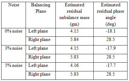
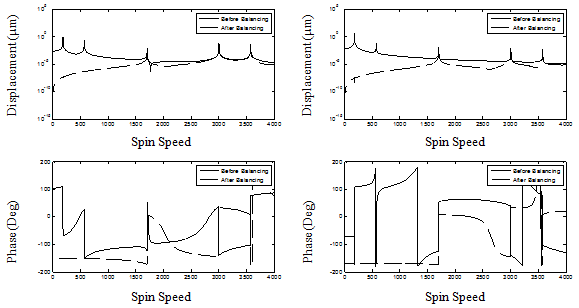
Fig. 13.44 Unbalance responses before and after balancing without damping and no noise (left) the left measuring plane (b) the right measuring plane