Solution: To numerically simulate unbalance responses of the above rotor-bearing system, the FEM is applied for modeling. As a first step we divided the shaft into 9 numbers of elements as shown in Fig.13.32 with element numbers and node numbers.
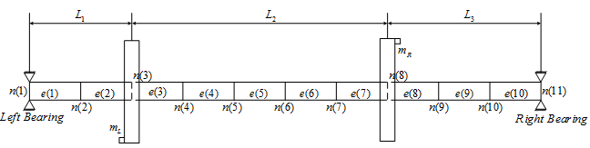
Fig. 13.32 A rotor with distributed unbalance divided into 10 elements
In Fig. 13.32 n(r)represents the  node and e(r) represents th element. Elemental equations are written and assembled to give global equations. After application of boundary conditions of simply supported ends at nodes 1 and 10 a reduced form of governing finite elemental equations are obtained. Unbalance responses are obtained without and with trial masses keeping residual unbalances (discrete and continuous) all the time in rotor system. Then unbalance response of amplitudes and phases at selected nodes (i.e., node numbers 4 and 7) are plotted (in semi-log) as a function of spin speed of rotor from 0 to 2000 rad/s.
Formulation for FEM the numerical simulation:
Elemental equation of motion of a particular element is given by

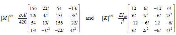
Here the consistence mass and stiffness matrices for a single element are
For element numbers 1 & 2, the length of an element is 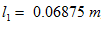 the mass matrix can be written as
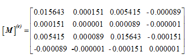
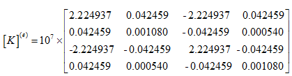
and stiffness matrix can be written as
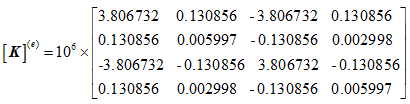
For element numbers 3 to 7, the length of each element is  the mass and stiffness matrix can be written as
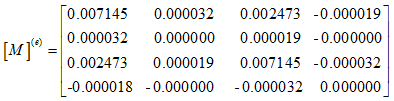
and stiffness matrix can be written as
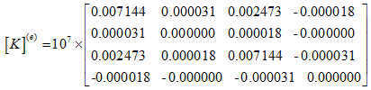
and for element numbers 8 to 10, the length of each element is  and the corresponding values of the mass and stiffness matrices are given by
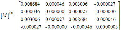
and the stiffness matrix is given by